How to Use exg sensor: Examples, Pinouts, and Specs
Introduction
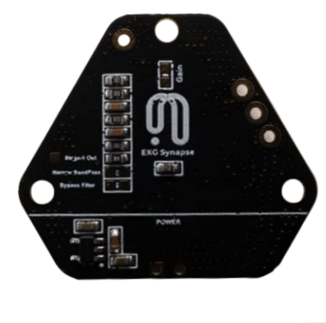
The Neophony Synaps EXG Sensor is a state-of-the-art electronic component designed to measure bio-electrical signals from the human body. This sensor is capable of capturing a wide range of physiological signals, including electrocardiogram (ECG), electromyogram (EMG), and electroencephalogram (EEG) data. Common applications of the Synaps EXG Sensor include heart rate monitoring, muscle activity detection, and brain wave analysis, making it an invaluable tool in medical diagnostics, sports science, and biofeedback applications.
Explore Projects Built with exg sensor
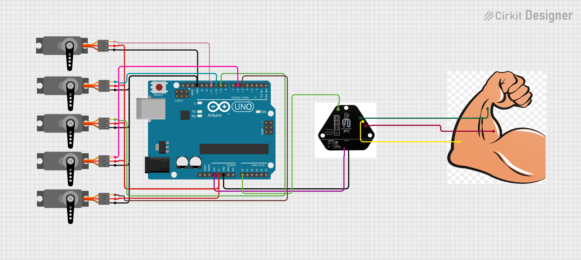

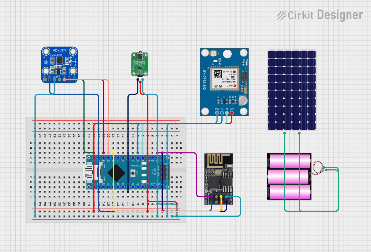
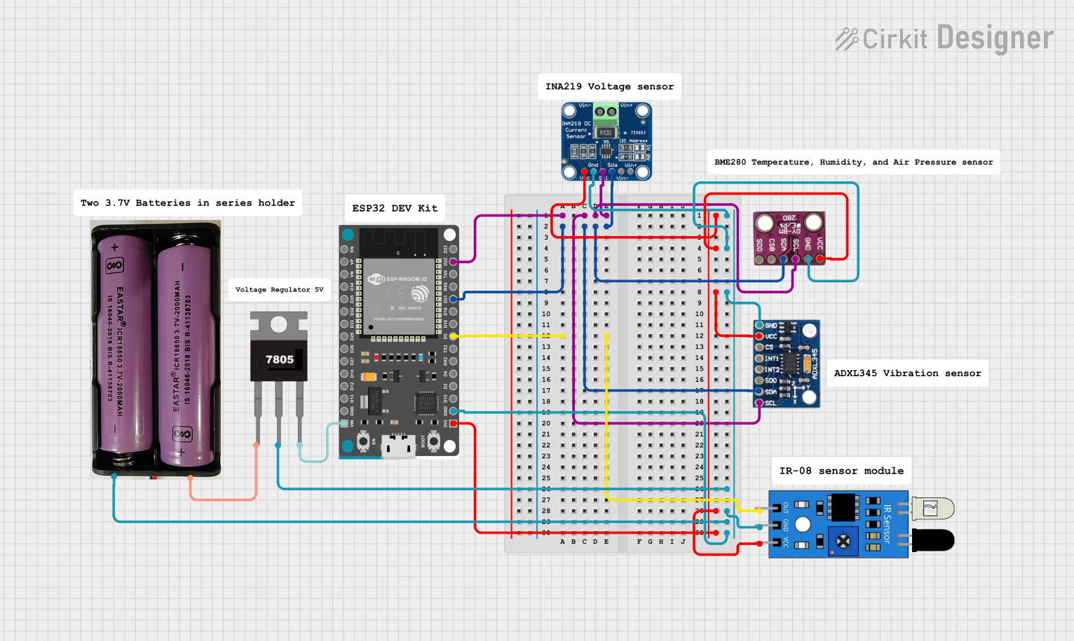
Explore Projects Built with exg sensor
Technical Specifications
General Specifications
| Parameter | Value | Description |
|---|---|---|
| Supply Voltage | 3.3V - 5V | Operating voltage range for the sensor. |
| Output Signal Type | Analog | The sensor outputs an analog voltage. |
| Operating Current | 10mA (typical) | Typical current draw during operation. |
| Frequency Response | 0.1Hz - 100Hz | Range of frequencies the sensor can detect. |
| Gain | Adjustable | User-configurable gain for signal amplification. |
Pin Configuration
| Pin Number | Name | Description |
|---|---|---|
| 1 | VCC | Power supply input (3.3V - 5V). |
| 2 | GND | Ground reference for the sensor. |
| 3 | OUT | Analog output signal from the sensor. |
| 4 | REF | Reference voltage for the analog output. |
| 5 | GAIN | Gain control input (analog or digital signal). |
Usage Instructions
Circuit Integration
- Connect the VCC pin to a 3.3V or 5V power supply.
- Attach the GND pin to the common ground in your circuit.
- The OUT pin should be connected to an analog input on your microcontroller, such as an Arduino UNO.
- The REF pin is typically connected to a mid-supply reference voltage.
- The GAIN pin can be connected to a potentiometer or a digital-to-analog converter (DAC) to adjust the gain.
Best Practices
- Ensure that the power supply is stable and within the specified voltage range to prevent sensor damage.
- Use shielded cables for the OUT pin to minimize noise and interference.
- Keep the sensor away from electrical noise sources such as motors and high-frequency signals.
- For accurate readings, the sensor should be properly attached to the body with suitable conductive gel or pads.
Example Arduino Code
// Define the analog pin connected to the EXG sensor
const int exgPin = A0;

void setup() {
  // Initialize serial communication at 9600 baud rate
  Serial.begin(9600);
}

void loop() {
  // Read the value from the EXG sensor
  int exgValue = analogRead(exgPin);

  // Convert the analog reading (which goes from 0 - 1023) to a voltage (0 - 5V)
  float voltage = exgValue * (5.0 / 1023.0);

  // Print the voltage to the Serial Monitor
  Serial.println(voltage);

  // Delay for a bit to get stable readings
  delay(10);
}
Troubleshooting and FAQs
Common Issues
- Inaccurate Readings: Ensure that the sensor is properly attached and that the body area is clean before application.
- No Signal Detected: Check all connections, especially the VCC and GND pins, and ensure that the sensor is powered.
- Signal Too Weak or Too Strong: Adjust the gain using the GAIN pin to obtain an optimal signal level.
FAQs
Q: Can the Synaps EXG Sensor be used with a 5V system? A: Yes, the sensor is compatible with both 3.3V and 5V systems.
Q: How can I reduce noise in the signal? A: Use shielded cables, keep the sensor away from noise sources, and ensure a stable power supply.
Q: What should I do if the sensor is not responding? A: Verify the power supply, check all connections, and ensure that the sensor is not damaged.
For further assistance, please contact Neophony support or refer to the detailed Synaps EXG Sensor manual.