Cirkit Designer Logo
Cirkit Designer
Your all-in-one circuit design IDE
Home / 
Component Documentation

How to Use MPU-9250/6500/9255: Examples, Pinouts, and Specs

Image of MPU-9250/6500/9255
Cirkit Designer LogoDesign with MPU-9250/6500/9255 in Cirkit Designer

Introduction

The MPU-9250/6500/9255 is a multi-faceted motion tracking device that integrates a 3-axis gyroscope, 3-axis accelerometer, and a 3-axis magnetometer. This 9-axis sensor is capable of providing comprehensive motion sensing and orientation data, making it an ideal component for a wide range of applications including but not limited to robotics, wearable technology, drones, and augmented reality.

Explore Projects Built with MPU-9250/6500/9255

Use Cirkit Designer to design, explore, and prototype these projects online. Some projects support real-time simulation. Click "Open Project" to start designing instantly!
Arduino Nano and MPU-9250 Based Motion Tracking System
Image of MPU-9250: A project utilizing MPU-9250/6500/9255 in a practical application
This circuit consists of an Arduino Nano microcontroller connected to an MPU-9250/6500/9255 sensor module. The Arduino Nano provides power and ground to the sensor and communicates with it via the I2C protocol using the A4 (SDA) and A5 (SCL) pins.
Cirkit Designer LogoOpen Project in Cirkit Designer
MPU-9250 and NUCLEO-F072RB Based Motion Sensing System
Image of MPU-9250 I2C: A project utilizing MPU-9250/6500/9255 in a practical application
This circuit interfaces an MPU-9250/6500/9255 sensor module with a NUCLEO-F072RB microcontroller board. The sensor module is powered by the 3.3V supply from the microcontroller and communicates via the I2C protocol using the SCL and SDA lines.
Cirkit Designer LogoOpen Project in Cirkit Designer
ESP32-Controlled Multi-MPU6050 and MPU9250 IMU Data Aggregator
Image of gant vr: A project utilizing MPU-9250/6500/9255 in a practical application
This circuit features an ESP32 microcontroller interfaced with multiple MPU-6050 sensors and a single MPU-9250 sensor through an Adafruit TCA9548A I2C multiplexer, allowing for the reading of multiple inertial measurement units (IMUs) over the same I2C bus. The ESP32 collects and processes acceleration and gyroscopic data from the sensors to calculate angles in the X and Y axes. Power management is handled by a TP4056 charging module and an AMS1117 voltage regulator, which together with two 18650 Li-ion batteries, provide a stable power supply for the microcontroller and sensors.
Cirkit Designer LogoOpen Project in Cirkit Designer
Arduino Nano and MPU-9250 Motion Sensor Interface
Image of tilt compass: A project utilizing MPU-9250/6500/9255 in a practical application
This circuit interfaces an Arduino Nano with an MPU-9250/6500/9255 sensor module to read and process motion and orientation data. The Arduino Nano communicates with the MPU sensor via SPI, and the provided code initializes the sensor, performs a self-test, and reads data from the sensor to output gyroscope, accelerometer, and quaternion values.
Cirkit Designer LogoOpen Project in Cirkit Designer

Explore Projects Built with MPU-9250/6500/9255

Use Cirkit Designer to design, explore, and prototype these projects online. Some projects support real-time simulation. Click "Open Project" to start designing instantly!
Image of MPU-9250: A project utilizing MPU-9250/6500/9255 in a practical application
Arduino Nano and MPU-9250 Based Motion Tracking System
This circuit consists of an Arduino Nano microcontroller connected to an MPU-9250/6500/9255 sensor module. The Arduino Nano provides power and ground to the sensor and communicates with it via the I2C protocol using the A4 (SDA) and A5 (SCL) pins.
Cirkit Designer LogoOpen Project in Cirkit Designer
Image of MPU-9250 I2C: A project utilizing MPU-9250/6500/9255 in a practical application
MPU-9250 and NUCLEO-F072RB Based Motion Sensing System
This circuit interfaces an MPU-9250/6500/9255 sensor module with a NUCLEO-F072RB microcontroller board. The sensor module is powered by the 3.3V supply from the microcontroller and communicates via the I2C protocol using the SCL and SDA lines.
Cirkit Designer LogoOpen Project in Cirkit Designer
Image of gant vr: A project utilizing MPU-9250/6500/9255 in a practical application
ESP32-Controlled Multi-MPU6050 and MPU9250 IMU Data Aggregator
This circuit features an ESP32 microcontroller interfaced with multiple MPU-6050 sensors and a single MPU-9250 sensor through an Adafruit TCA9548A I2C multiplexer, allowing for the reading of multiple inertial measurement units (IMUs) over the same I2C bus. The ESP32 collects and processes acceleration and gyroscopic data from the sensors to calculate angles in the X and Y axes. Power management is handled by a TP4056 charging module and an AMS1117 voltage regulator, which together with two 18650 Li-ion batteries, provide a stable power supply for the microcontroller and sensors.
Cirkit Designer LogoOpen Project in Cirkit Designer
Image of tilt compass: A project utilizing MPU-9250/6500/9255 in a practical application
Arduino Nano and MPU-9250 Motion Sensor Interface
This circuit interfaces an Arduino Nano with an MPU-9250/6500/9255 sensor module to read and process motion and orientation data. The Arduino Nano communicates with the MPU sensor via SPI, and the provided code initializes the sensor, performs a self-test, and reads data from the sensor to output gyroscope, accelerometer, and quaternion values.
Cirkit Designer LogoOpen Project in Cirkit Designer

Technical Specifications

Key Technical Details

  • Supply Voltage (VDD): 2.4V - 3.6V
  • Operating Current: 3.2mA
  • Gyroscope Range: ±250, ±500, ±1000, ±2000 degrees/sec
  • Accelerometer Range: ±2g, ±4g, ±8g, ±16g
  • Magnetometer Range (MPU-9250/9255 only): ±4800 µT
  • Communication: I2C and SPI
  • Operating Temperature: -40°C to +85°C

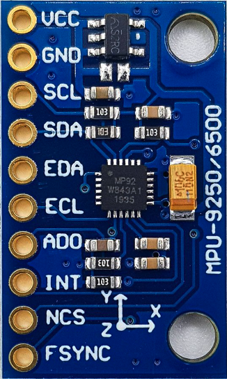
Pin Configuration and Descriptions

Pin Number Name Description
1 VDD Power supply (2.4V - 3.6V)
2 GND Ground
3 SCL/SPC I2C clock / SPI clock
4 SDA/SDI I2C data / SPI data input
5 AD0/SDO I2C address select / SPI data output
6 NCS SPI chip select (active low)
7 INT Interrupt output (active high)
8 FSYNC Frame synchronization (optional)

Usage Instructions

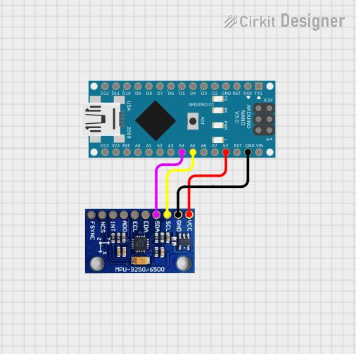
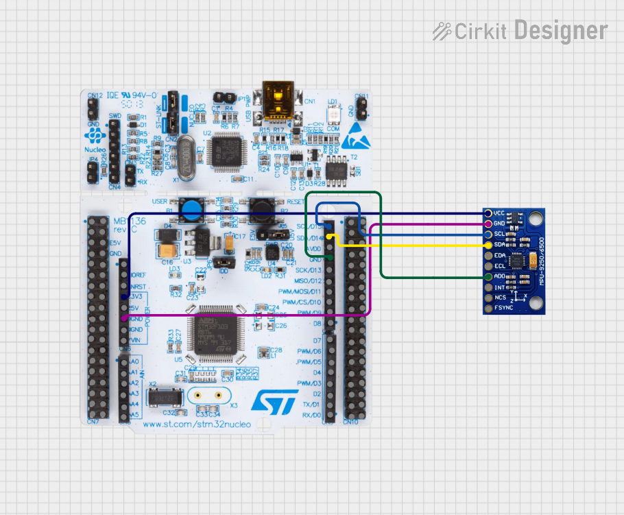
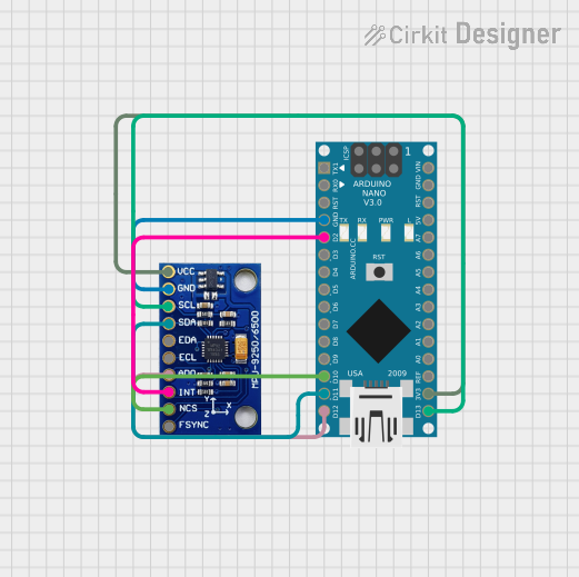
Integration into a Circuit

To use the MPU-9250/6500/9255 in a circuit:

  1. Connect VDD to a 2.4V - 3.6V power supply.
  2. Connect GND to the ground of your system.
  3. For I2C communication, connect SCL to the I2C clock and SDA to the I2C data line.
  4. For SPI communication, connect SPC to the SPI clock, SDI to the SPI data input, SDO to the SPI data output, and NCS to the SPI chip select.
  5. Optionally, connect INT to an interrupt pin on your microcontroller to use the interrupt feature.
  6. Optionally, connect FSYNC to synchronize frames if required by your application.

Best Practices

  • Use pull-up resistors on the I2C data and clock lines.
  • Ensure that the power supply is stable and within the specified voltage range.
  • When using SPI, ensure that the NCS line is held high when the device is not in use.
  • For accurate readings, calibrate the sensors following the manufacturer's guidelines.

Example Code for Arduino UNO

#include <Wire.h>

// MPU-9250 I2C address (depends on AD0 pin, here we assume it's connected to GND)
const int MPU9250_ADDRESS = 0x68;

void setup() {
  Wire.begin(); // Initialize I2C
  Serial.begin(115200); // Start serial communication at 115200 baud
  setupMPU9250(); // Setup MPU-9250 registers
}

void loop() {
  // Read sensor data and print it
  readSensorData();
  delay(100); // Delay for readability
}

void setupMPU9250() {
  // Wake up MPU-9250
  writeMPU9250(MPU9250_ADDRESS, 0x6B, 0x00);
  // Configure gyroscope and accelerometer
  // This is a basic configuration and should be adjusted for your application
  writeMPU9250(MPU9250_ADDRESS, 0x1B, 0x00); // Set gyroscope to ±250 degrees/sec
  writeMPU9250(MPU9250_ADDRESS, 0x1C, 0x00); // Set accelerometer to ±2g
}

void readSensorData() {
  // Read accelerometer and gyroscope data
  // Implement data reading logic here
}

void writeMPU9250(byte address, byte reg, byte data) {
  Wire.beginTransmission(address);
  Wire.write(reg);
  Wire.write(data);
  Wire.endTransmission();
}

Troubleshooting and FAQs

Common Issues

  • No data is being read from the sensor: Ensure that the I2C or SPI connections are correct and secure. Check that the correct communication protocol is being used in your code.
  • Inaccurate sensor readings: Calibrate the sensors as per the manufacturer's instructions. Ensure that the sensor is not being affected by magnetic fields or vibrations.
  • Intermittent connection: Check for loose connections and ensure that the pull-up resistors are correctly installed on the I2C lines.

FAQs

Q: Can the MPU-9250/6500/9255 be used with both I2C and SPI simultaneously? A: No, you must choose either I2C or SPI for communication with the MPU-9250/6500/9255.

Q: What is the purpose of the AD0/SDO pin? A: The AD0/SDO pin is used to set the I2C address of the device when using I2C communication. For SPI, it serves as the data output pin.

Q: How do I calibrate the MPU-9250/6500/9255? A: Calibration involves capturing sensor data at known orientations and then using these values to correct for offsets and scaling errors. Refer to the manufacturer's documentation for detailed calibration procedures.

Q: What should I do if the MPU-9250/6500/9255 is not responding? A: Verify the power supply, check all connections, and ensure that the correct I2C address or SPI settings are being used. Reset the device and try initializing it again with the correct configuration settings.