How to Use PNP Transistor (ECB): Examples, Pinouts, and Specs

Introduction
A PNP transistor is a type of bipolar junction transistor (BJT) that consists of a layer of N-doped semiconductor (the base) sandwiched between two layers of P-doped material (the emitter and collector). Unlike its NPN counterpart, the PNP transistor is designed such that the current flows from the emitter to the collector with the base controlling the flow. This component is essential in various electronic applications, including amplification and switching operations.
Explore Projects Built with PNP Transistor (ECB)

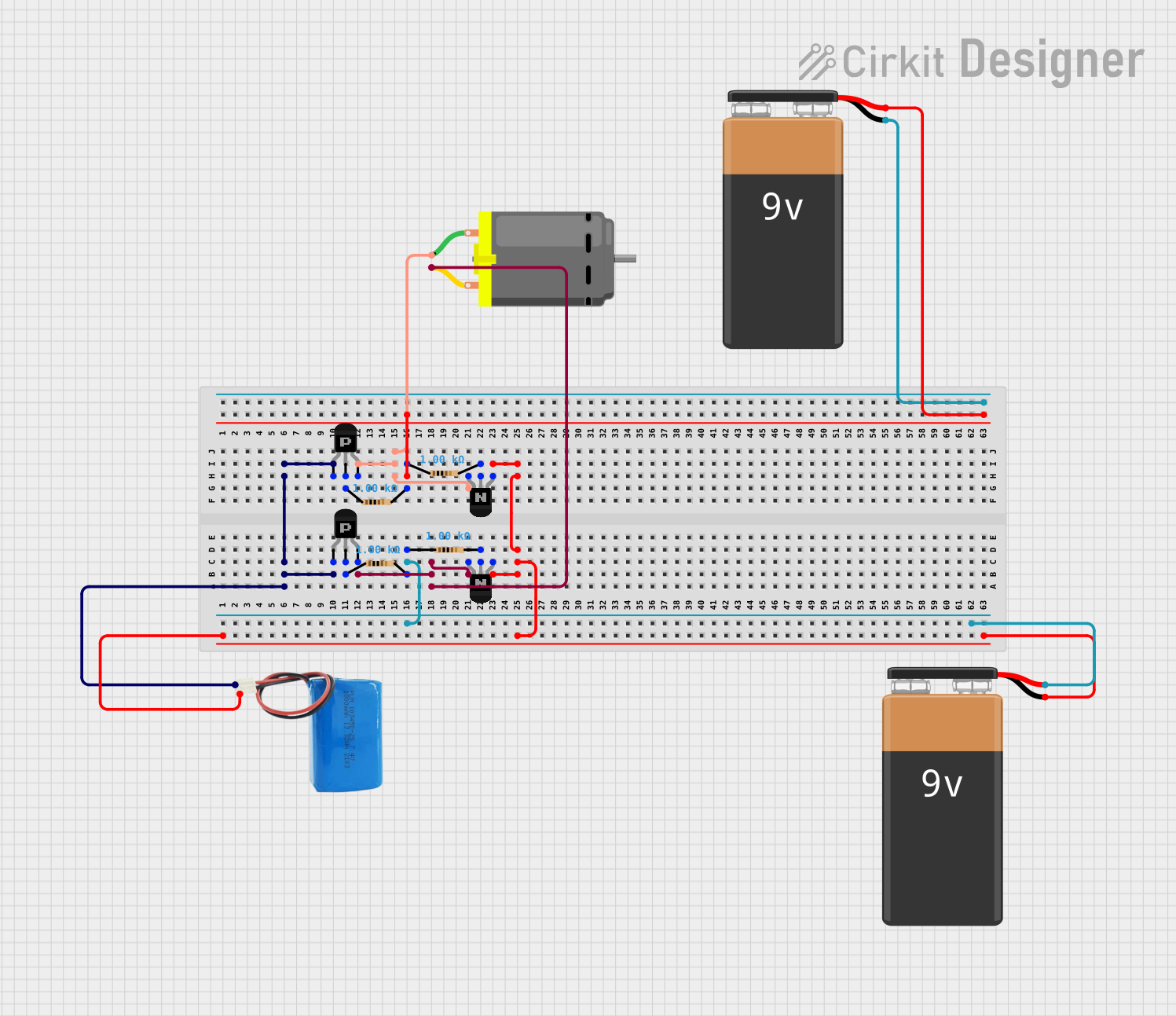
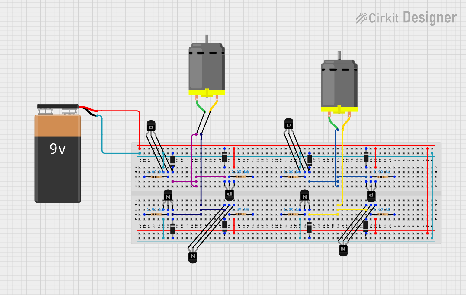
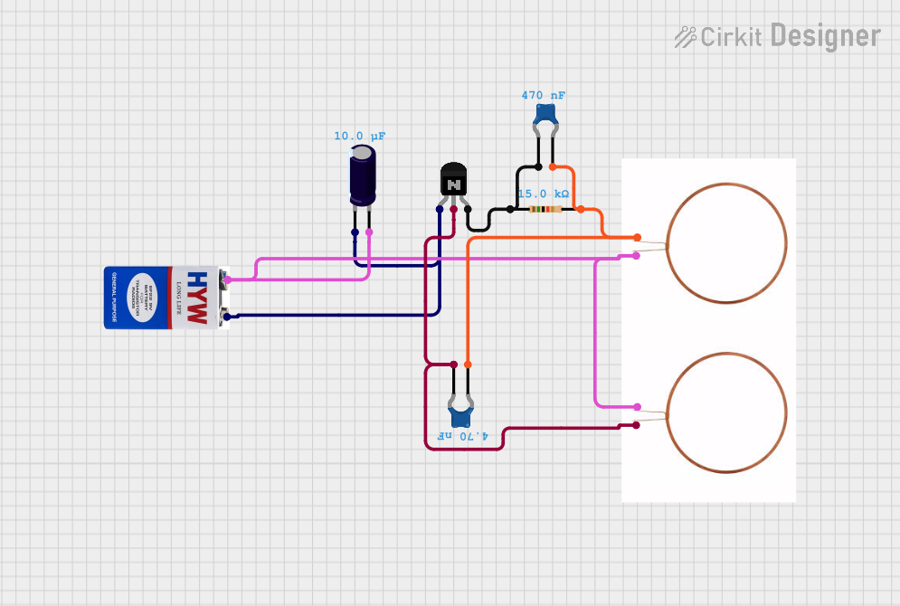
Explore Projects Built with PNP Transistor (ECB)
Common Applications and Use Cases
- Signal Amplification
- Switching in Power Circuits
- Audio Amplifiers
- Inverting Signals
- Motor Control Circuits
Technical Specifications
Key Technical Details
- Type: PNP Bipolar Junction Transistor
- Maximum Collector-Emitter Voltage (Vce): Specified by manufacturer (e.g., -30V)
- Maximum Collector-Base Voltage (Vcb): Specified by manufacturer (e.g., -60V)
- Maximum Emitter-Base Voltage (Veb): Specified by manufacturer (e.g., -5V)
- Maximum Collector Current (Ic): Specified by manufacturer (e.g., -100mA)
- Power Dissipation (Pd): Specified by manufacturer (e.g., 625mW)
Pin Configuration and Descriptions
| Pin Number | Name | Description |
|---|---|---|
| 1 | Emitter (E) | Current flows out through this terminal |
| 2 | Collector (C) | Current flows in through this terminal |
| 3 | Base (B) | Controls the transistor's operation |
Usage Instructions
How to Use the Component in a Circuit
- Biasing the Transistor: To turn on a PNP transistor, ensure the base is at a lower voltage than the emitter.
- Connecting the Load: The load should be connected to the collector terminal and the positive supply.
- Base Resistor: A resistor is often needed between the base and the signal source to limit the base current.
Important Considerations and Best Practices
- Polarity: Ensure the correct polarity when connecting the power supply; PNP transistors require a negative voltage at the base to turn on.
- Saturation: To fully saturate the transistor, the base-emitter voltage should be higher than the base-collector voltage.
- Heat Sinking: For high-power applications, a heat sink may be necessary to dissipate heat and prevent damage.
Example Circuit with Arduino UNO
// Example code to control a PNP transistor with an Arduino UNO

const int basePin = 3; // Connect to the base of the transistor

void setup() {
  pinMode(basePin, OUTPUT);
}

void loop() {
  digitalWrite(basePin, LOW); // Turns the PNP transistor ON
  delay(1000);                // Wait for 1 second
  digitalWrite(basePin, HIGH); // Turns the PNP transistor OFF
  delay(1000);                // Wait for 1 second
}
Note: In this example, the Arduino pin is connected to the base of the PNP transistor through a suitable resistor. The emitter of the transistor is connected to the positive voltage supply, and the collector is connected to the load that needs to be switched.
Troubleshooting and FAQs
Common Issues Users Might Face
- Transistor Does Not Switch: Check if the base is sufficiently negative relative to the emitter.
- Excessive Heat: Ensure the current and power ratings are not exceeded, and proper heat sinking is used.
- Unexpected Behavior: Verify that the transistor is not damaged and that all connections are correct.
Solutions and Tips for Troubleshooting
- Base Voltage: Use a multimeter to check the voltage at the base of the transistor.
- Current Limiting: Always use a base resistor to limit the current into the base.
- Component Testing: Test the transistor with a multimeter in diode mode to ensure it is functioning properly.
FAQs
Q: Can I use a PNP transistor to switch a high current load? A: Yes, but ensure the transistor's current and power ratings are suitable for the load.
Q: How do I choose the base resistor value? A: The base resistor value depends on the desired base current, which is typically a fraction of the collector current (Ic). Use Ohm's law and the transistor's datasheet to determine the appropriate value.
Q: What happens if I reverse the collector and emitter? A: The transistor will not function properly as it is designed to operate with current flowing from the emitter to the collector.