
How to Use PZEM-016: Examples, Pinouts, and Specs

 Design with PZEM-016 in Cirkit Designer
Introduction
The PZEM-016 is a multifunctional energy meter designed for monitoring and measuring key electrical parameters in AC circuits. Manufactured by PZEM, this device provides accurate readings of voltage, current, power, energy consumption, and frequency. It is equipped with a digital display for real-time monitoring and supports communication via Modbus RTU (RS485), making it suitable for integration into automated systems.
Explore Projects Built with PZEM-016
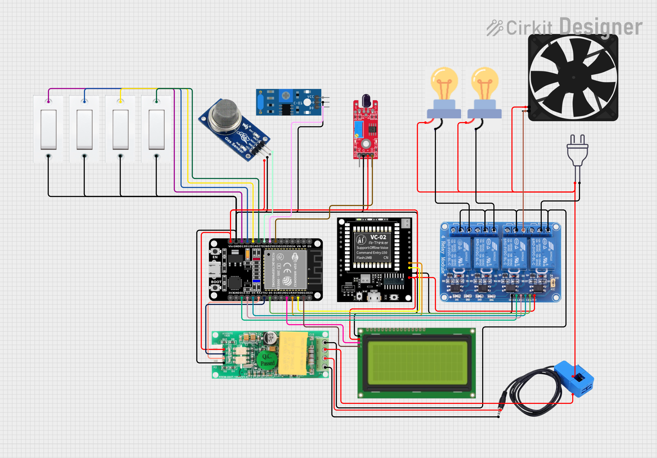 Open Project in Cirkit Designer
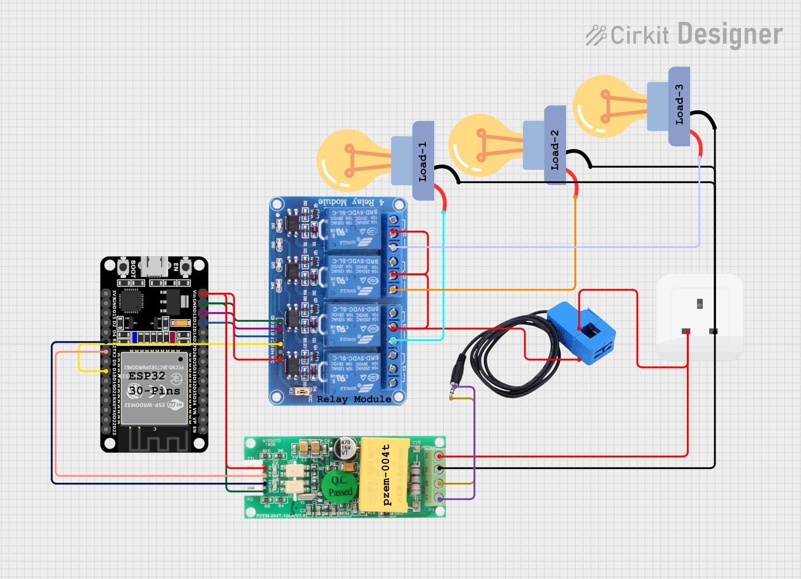 Open Project in Cirkit Designer
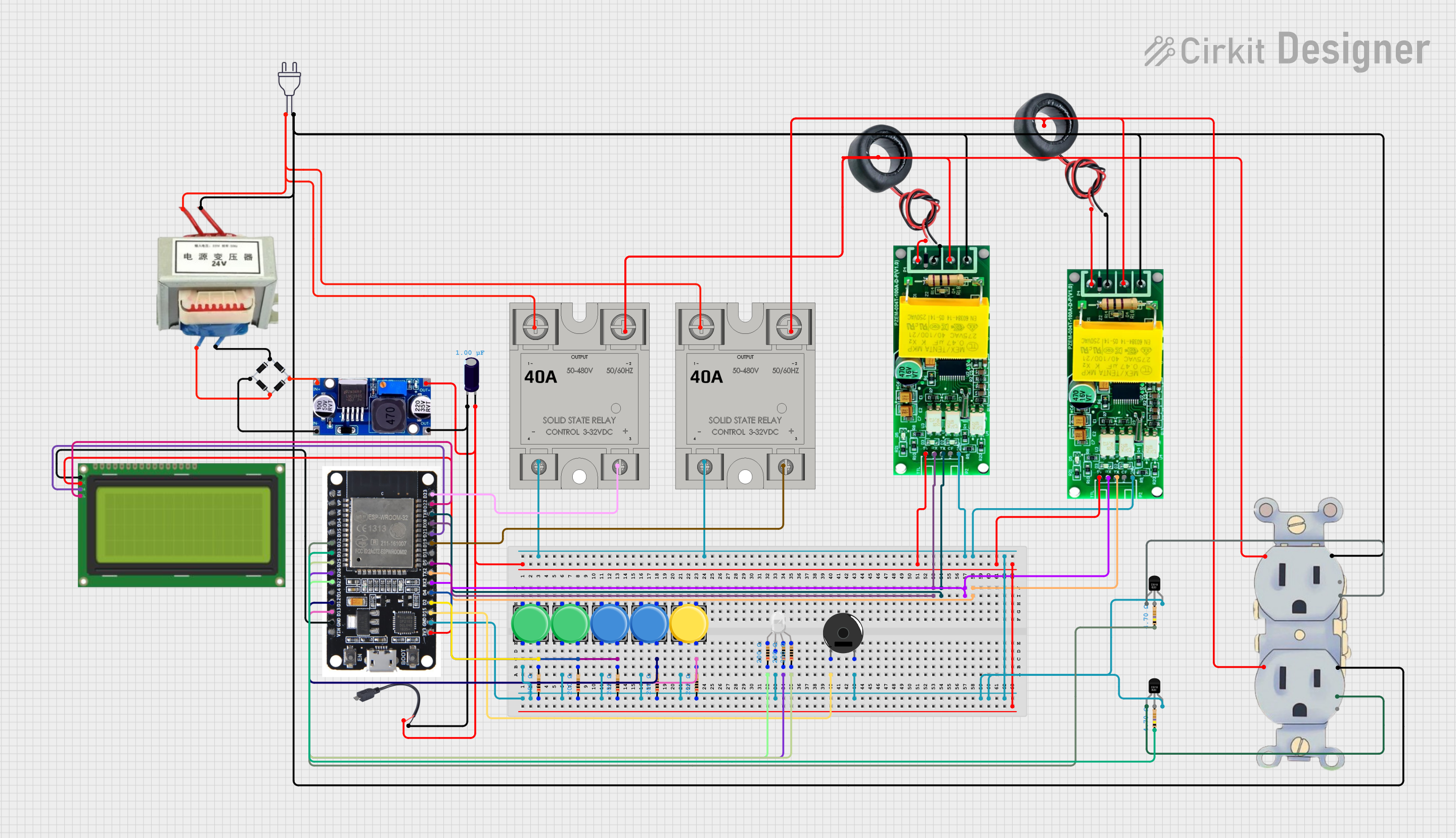 Open Project in Cirkit Designer
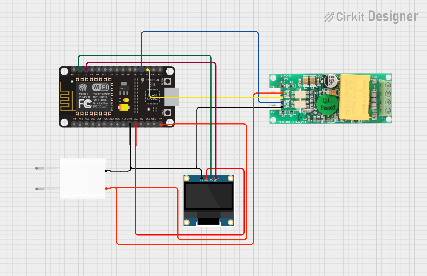 Open Project in Cirkit Designer
Explore Projects Built with PZEM-016
Open Project in Cirkit DesignerOpen Project in Cirkit DesignerOpen Project in Cirkit DesignerOpen Project in Cirkit DesignerCommon Applications and Use Cases
- Energy management in residential, commercial, and industrial settings
- Monitoring power consumption of appliances and machinery
- Integration into smart home or IoT systems for energy tracking
- Load analysis and optimization in electrical systems
- Educational and research purposes in electrical engineering
Technical Specifications
Key Technical Details
| Parameter | Specification |
|---|---|
| Operating Voltage | 80V - 260V AC |
| Measurement Voltage Range | 80V - 260V AC |
| Current Measurement Range | 0A - 100A (with external current transformer) |
| Power Measurement Range | 0W - 22kW |
| Energy Measurement Range | 0kWh - 9999kWh |
| Frequency Range | 45Hz - 65Hz |
| Communication Protocol | Modbus RTU (RS485) |
| Baud Rate | 9600 bps |
| Accuracy | ±0.5% |
| Operating Temperature | -10°C to 60°C |
| Dimensions | 96mm x 58mm x 24mm |
Pin Configuration and Descriptions
The PZEM-016 has a set of terminals for power input, load connection, and RS485 communication. Below is the pin configuration:
Power and Load Terminals
| Terminal Label | Description |
|---|---|
| L (Line) | Connect to the live wire of the AC input |
| N (Neutral) | Connect to the neutral wire of the AC input |
| CT (Current Transformer) | Connect to the external current transformer for current measurement |
RS485 Communication Terminals
| Terminal Label | Description |
|---|---|
| A | RS485 communication line A |
| B | RS485 communication line B |
Usage Instructions
How to Use the PZEM-016 in a Circuit
- Power Connection: Connect the live (L) and neutral (N) wires of the AC input to the corresponding terminals on the PZEM-016.
- Current Transformer (CT) Connection: Attach the external current transformer to the CT terminals. Ensure the CT is properly clamped around the live wire of the load.
- RS485 Communication: Connect the A and B terminals to an RS485-to-USB converter or an RS485 interface on a microcontroller for data communication.
- Load Connection: Connect the load to the output terminals of the PZEM-016.
Important Considerations and Best Practices
- Ensure all connections are secure and insulated to prevent electrical hazards.
- Use the appropriate current transformer (rated for up to 100A) for accurate current measurement.
- Avoid exposing the device to extreme temperatures or humidity.
- When using RS485 communication, ensure proper termination resistors are used to avoid signal reflections.
- Always power off the circuit before making any connections or modifications.
Example: Connecting PZEM-016 to Arduino UNO
The PZEM-016 can be interfaced with an Arduino UNO using an RS485-to-TTL converter. Below is an example code snippet for reading data from the PZEM-016:
#include <ModbusMaster.h>

// Create an instance of ModbusMaster
ModbusMaster node;

// Define RS485 communication pins
#define RE_DE 2  // Pin to control RS485 direction

void preTransmission() {
  digitalWrite(RE_DE, HIGH); // Enable RS485 transmission
}

void postTransmission() {
  digitalWrite(RE_DE, LOW);  // Enable RS485 reception
}

void setup() {
  Serial.begin(9600);        // Initialize serial communication
  pinMode(RE_DE, OUTPUT);    // Set RS485 control pin as output
  digitalWrite(RE_DE, LOW);  // Set RS485 to reception mode

  node.begin(1, Serial);     // Initialize Modbus communication (ID: 1)
  node.preTransmission(preTransmission);
  node.postTransmission(postTransmission);
}

void loop() {
  uint8_t result;
  uint16_t data[6];

  // Read voltage (register 0x0000)
  result = node.readInputRegisters(0x0000, 1);
  if (result == node.ku8MBSuccess) {
    Serial.print("Voltage: ");
    Serial.print(node.getResponseBuffer(0) / 10.0); // Convert to volts
    Serial.println(" V");
  }

  // Add similar code for current, power, energy, and frequency
  delay(1000); // Wait 1 second before next reading
}
Troubleshooting and FAQs
Common Issues and Solutions
No Data on RS485 Communication
- Cause: Incorrect wiring or baud rate mismatch.
- Solution: Verify the A and B connections and ensure the baud rate is set to 9600 bps.
Inaccurate Measurements
- Cause: Improper current transformer installation or incorrect wiring.
- Solution: Ensure the CT is clamped around the live wire and the connections are secure.
Device Not Powering On
- Cause: Faulty power connection or insufficient voltage.
- Solution: Check the live and neutral connections and ensure the input voltage is within the 80V-260V range.
Intermittent Communication Failures
- Cause: Long RS485 cable or missing termination resistors.
- Solution: Use termination resistors (120Ω) at both ends of the RS485 bus and minimize cable length.
FAQs
Q: Can the PZEM-016 measure DC circuits?
A: No, the PZEM-016 is designed for AC circuits only.Q: What is the maximum current the PZEM-016 can measure?
A: The device can measure up to 100A using the appropriate current transformer.Q: Can I use multiple PZEM-016 devices on the same RS485 bus?
A: Yes, each device can be assigned a unique Modbus ID for multi-device communication.Q: Is the PZEM-016 compatible with other microcontrollers besides Arduino?
A: Yes, it can be used with any microcontroller that supports Modbus RTU communication.
This concludes the documentation for the PZEM-016 multifunctional energy meter.