How to Use Voltmetre 24V + charger: Examples, Pinouts, and Specs
Introduction
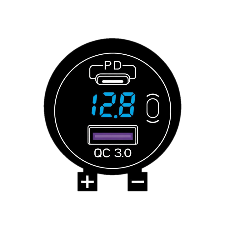
The Voltmetre 24V + Charger (Manufacturer: DC, Part ID: 1) is a versatile electronic component designed to measure voltage levels up to 24V while simultaneously functioning as a charging module for compatible devices. This dual-purpose component is ideal for monitoring and maintaining power systems in various applications, such as automotive, renewable energy setups, and portable electronics.
Explore Projects Built with Voltmetre 24V + charger


Explore Projects Built with Voltmetre 24V + charger
Common Applications and Use Cases
- Monitoring battery voltage in automotive and marine systems
- Charging 12V or 24V batteries in solar power systems
- Voltage measurement in DIY electronics projects
- Power supply monitoring in industrial equipment
Technical Specifications
The Voltmetre 24V + Charger is designed to provide accurate voltage readings and efficient charging capabilities. Below are the key technical details:
General Specifications
| Parameter | Value |
|---|---|
| Input Voltage Range | 6V to 30V |
| Output Voltage (Charging) | 5V, 12V, or 24V (selectable) |
| Maximum Output Current | 2A |
| Voltage Measurement Range | 0V to 24V |
| Measurement Accuracy | ±1% |
| Display Type | 7-segment LED (3 digits) |
| Operating Temperature | -10°C to 60°C |
| Dimensions | 50mm x 30mm x 20mm |
Pin Configuration and Descriptions
| Pin Name | Description |
|---|---|
| VIN+ | Positive input terminal for voltage measurement and power supply |
| VIN- | Negative input terminal (ground) |
| OUT+ | Positive output terminal for charging |
| OUT- | Negative output terminal for charging (ground) |
| MODE | Mode selection pin (used to toggle between voltage measurement and charging) |
Usage Instructions
How to Use the Component in a Circuit
Connecting the Voltmetre:
- Connect the
VIN+andVIN-pins to the power source or battery you want to monitor. - Ensure the input voltage does not exceed 30V to avoid damaging the component.
- Connect the
Using the Charging Function:
- Connect the
OUT+andOUT-pins to the device or battery you want to charge. - Use the
MODEpin to switch to charging mode. Refer to the manufacturer's datasheet for specific mode selection instructions.
- Connect the
Voltage Measurement:
- When in voltage measurement mode, the LED display will show the real-time voltage of the connected power source.
Important Considerations and Best Practices
- Polarity: Always ensure correct polarity when connecting the component. Reversing the polarity may damage the module.
- Heat Dissipation: If the module is used for charging at high currents (e.g., 2A), ensure proper ventilation or use a heatsink to prevent overheating.
- Voltage Limits: Do not exceed the specified input voltage range (6V to 30V) to avoid permanent damage.
- Mode Selection: Use the
MODEpin carefully to toggle between measurement and charging modes. Incorrect mode selection may lead to improper operation.
Example: Using with Arduino UNO
The Voltmetre 24V + Charger can be interfaced with an Arduino UNO to monitor voltage levels programmatically. Below is an example code snippet:
// Example code to read voltage from the Voltmetre 24V + Charger
// using an Arduino UNO's analog input pin.

const int voltagePin = A0; // Connect VIN+ to A0 and VIN- to GND
const float referenceVoltage = 5.0; // Arduino's reference voltage (5V)
const int adcResolution = 1024; // 10-bit ADC resolution

void setup() {
  Serial.begin(9600); // Initialize serial communication
  pinMode(voltagePin, INPUT); // Set the voltage pin as input
}

void loop() {
  int adcValue = analogRead(voltagePin); // Read the analog value
  // Calculate the input voltage based on ADC value and reference voltage
  float inputVoltage = (adcValue * referenceVoltage) / adcResolution;

  // Print the voltage to the Serial Monitor
  Serial.print("Measured Voltage: ");
  Serial.print(inputVoltage);
  Serial.println(" V");

  delay(1000); // Wait for 1 second before the next reading
}
Troubleshooting and FAQs
Common Issues and Solutions
No Display on the LED Screen:
- Cause: Insufficient input voltage or incorrect wiring.
- Solution: Verify that the input voltage is within the 6V to 30V range and check the wiring.
Inaccurate Voltage Readings:
- Cause: Loose connections or interference from nearby components.
- Solution: Ensure all connections are secure and avoid placing the module near high-frequency devices.
Overheating During Charging:
- Cause: High current draw or poor ventilation.
- Solution: Reduce the charging current or improve airflow around the module.
Component Not Switching Modes:
- Cause: Faulty
MODEpin connection or incorrect operation. - Solution: Check the
MODEpin wiring and refer to the datasheet for proper mode selection.
- Cause: Faulty
FAQs
Q1: Can this module charge lithium-ion batteries?
A1: Yes, the module can charge lithium-ion batteries, but ensure the charging voltage and current are compatible with the battery specifications.
Q2: Is the module waterproof?
A2: No, the module is not waterproof. Use it in a dry environment or enclose it in a protective case.
Q3: Can I use this module to measure AC voltage?
A3: No, the module is designed for DC voltage measurement only. Measuring AC voltage may damage the component.
Q4: How do I reset the module?
A4: Disconnect the power supply and reconnect it to reset the module.