How to Use CC1101 Module: Examples, Pinouts, and Specs
Introduction
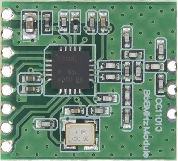
The CC1101 Module is a low-power sub-1 GHz transceiver designed for wireless communication in the ISM (Industrial, Scientific, and Medical) and SRD (Short-Range Device) frequency bands. It supports multiple modulation formats, including ASK, FSK, GFSK, and MSK, making it highly versatile for various applications. The module is widely used in remote control systems, wireless sensor networks, home automation, and industrial monitoring due to its low power consumption and robust performance.
Explore Projects Built with CC1101 Module


Explore Projects Built with CC1101 Module
Common Applications:
- Remote control systems (e.g., garage doors, drones)
- Wireless sensor networks
- Home automation systems
- Industrial monitoring and control
- Smart metering and telemetry
Technical Specifications
The CC1101 Module is packed with features that make it suitable for low-power and long-range wireless communication. Below are its key technical details:
Key Technical Details:
- Frequency Range: 300 MHz to 928 MHz (configurable)
- Modulation Formats: ASK, FSK, GFSK, MSK
- Data Rate: 0.6 kbps to 600 kbps
- Supply Voltage: 1.8 V to 3.6 V
- Current Consumption:
- Transmit: ~30 mA (at +10 dBm output power)
- Receive: ~15 mA
- Sleep Mode: <1 µA
- Output Power: Programmable up to +10 dBm
- Sensitivity: -116 dBm at 1.2 kbps
- Communication Interface: SPI (Serial Peripheral Interface)
- Operating Temperature Range: -40°C to +85°C
Pin Configuration and Descriptions:
The CC1101 Module typically comes with 10 pins. Below is the pinout and description:
| Pin | Name | Description |
|---|---|---|
| 1 | GND | Ground connection |
| 2 | VCC | Power supply (1.8 V to 3.6 V) |
| 3 | CSN | Chip Select (active low) for SPI communication |
| 4 | SCLK | SPI Clock input |
| 5 | MOSI | Master Out Slave In (data input to CC1101) |
| 6 | MISO | Master In Slave Out (data output from CC1101) |
| 7 | GDO0 | General-purpose digital output pin 0 (configurable for interrupts or status) |
| 8 | GDO2 | General-purpose digital output pin 2 (configurable for interrupts or status) |
| 9 | ANT | Antenna connection for RF signal transmission and reception |
| 10 | NC | Not connected (may vary depending on the module version) |
Usage Instructions
The CC1101 Module is easy to integrate into a circuit, thanks to its SPI interface and configurable settings. Below are the steps and best practices for using the module:
Steps to Use the CC1101 Module:
Power the Module:
- Connect the
VCCpin to a 3.3 V power supply and theGNDpin to ground. - Ensure the power supply is stable and within the specified voltage range.
- Connect the
Connect to a Microcontroller:
- Use the SPI interface to connect the
CSN,SCLK,MOSI, andMISOpins to the corresponding SPI pins on your microcontroller. - Configure the SPI clock speed to a maximum of 10 MHz for proper communication.
- Use the SPI interface to connect the
Antenna Connection:
- Attach a suitable antenna to the
ANTpin for optimal RF performance. The antenna should match the operating frequency of the module.
- Attach a suitable antenna to the
Configure the Module:
- Use the SPI interface to write configuration registers. These registers control parameters such as frequency, modulation, and data rate.
- Refer to the CC1101 datasheet for detailed register settings.
Transmit and Receive Data:
- Use the
GDO0andGDO2pins for interrupt handling or status monitoring during data transmission and reception.
- Use the
Best Practices:
- Use decoupling capacitors (e.g., 0.1 µF) near the
VCCpin to reduce noise and ensure stable operation. - Place the antenna away from other components to minimize interference.
- Use a level shifter if your microcontroller operates at 5 V logic levels, as the CC1101 operates at 3.3 V.
Example Code for Arduino UNO:
Below is an example of how to interface the CC1101 Module with an Arduino UNO for basic communication:
#include <SPI.h>

// Define CC1101 pins
#define CSN_PIN 10  // Chip Select
#define GDO0_PIN 2  // Interrupt pin for GDO0

void setup() {
  // Initialize SPI
  SPI.begin();
  pinMode(CSN_PIN, OUTPUT);
  pinMode(GDO0_PIN, INPUT);
  digitalWrite(CSN_PIN, HIGH); // Set CSN high to deselect CC1101

  Serial.begin(9600);
  Serial.println("Initializing CC1101...");

  // Example: Reset CC1101
  digitalWrite(CSN_PIN, LOW); // Select CC1101
  SPI.transfer(0x30);         // Send reset command
  digitalWrite(CSN_PIN, HIGH); // Deselect CC1101

  Serial.println("CC1101 Initialized.");
}

void loop() {
  // Example: Monitor GDO0 pin for interrupts
  if (digitalRead(GDO0_PIN) == HIGH) {
    Serial.println("Data received!");
  }
}
Notes:
- The above code demonstrates basic initialization and interrupt monitoring. For full functionality, you will need to configure the CC1101 registers based on your application requirements.
- Use a CC1101 library (e.g., Elechouse CC1101 library) for easier configuration and communication.
Troubleshooting and FAQs
Common Issues and Solutions:
No Communication with the Module:
- Ensure the SPI connections are correct and secure.
- Verify that the
CSNpin is properly toggled during SPI communication. - Check the power supply voltage and ensure it is within the specified range.
Poor RF Performance:
- Use a properly tuned antenna that matches the operating frequency.
- Avoid placing the module near metal objects or other RF sources.
Module Not Responding:
- Perform a hardware reset by toggling the
CSNpin or sending the reset command via SPI. - Check for any loose connections or soldering issues.
- Perform a hardware reset by toggling the
Interference with Other Devices:
- Configure the module to operate on a frequency that is less crowded.
- Use proper shielding and grounding techniques to minimize interference.
FAQs:
Q: Can the CC1101 Module operate at 5 V?
A: No, the CC1101 operates at 1.8 V to 3.6 V. Use a level shifter if interfacing with a 5 V microcontroller.Q: What is the maximum range of the CC1101 Module?
A: The range depends on factors such as antenna design, operating frequency, and environmental conditions. Typically, it can achieve up to 500 meters in open space.Q: Can I use the CC1101 for two-way communication?
A: Yes, the CC1101 supports both transmission and reception, making it suitable for two-way communication.Q: Is there a library available for Arduino?
A: Yes, libraries such as the Elechouse CC1101 library simplify the configuration and use of the module with Arduino.
By following this documentation, you can effectively integrate the CC1101 Module into your wireless communication projects.