How to Use Monster Motor Driver vnh2sp30: Examples, Pinouts, and Specs
Introduction
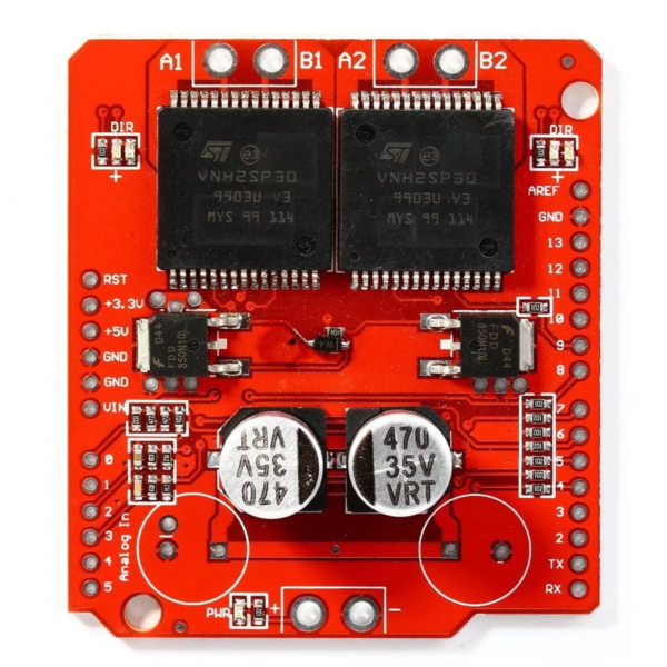
The Monster Motor Driver VNH2SP30 is a high-power motor driver designed to control DC motors with high current ratings. It is capable of handling up to 30A of continuous current and features built-in protection mechanisms, including overcurrent and thermal overload protection. This makes it an ideal choice for applications requiring robust and reliable motor control.
Explore Projects Built with Monster Motor Driver vnh2sp30


Explore Projects Built with Monster Motor Driver vnh2sp30
Common Applications and Use Cases
- Robotics and automation systems
- Electric vehicles and scooters
- Conveyor belts and industrial machinery
- High-power RC vehicles
- DIY projects involving large DC motors
Technical Specifications
The Monster Motor Driver VNH2SP30 is a dual full-bridge driver IC that can control two DC motors or one stepper motor. Below are its key technical details:
Key Technical Details
| Parameter | Value |
|---|---|
| Operating Voltage | 5.5V to 16V |
| Continuous Current | 30A per channel |
| Peak Current | 60A per channel |
| Logic Voltage | 3.3V or 5V (logic level compatible) |
| PWM Frequency | Up to 20 kHz |
| Thermal Shutdown | Yes |
| Overcurrent Protection | Yes |
| Dimensions | 60mm x 50mm x 15mm |
Pin Configuration and Descriptions
The Monster Motor Driver VNH2SP30 typically comes in a breakout board format. Below is the pin configuration:
| Pin Name | Description |
|---|---|
| VIN | Motor power supply (5.5V to 16V) |
| GND | Ground connection |
| INA1, INA2 | Input pins for motor A direction control |
| INB1, INB2 | Input pins for motor B direction control |
| PWM_A, PWM_B | PWM input pins for motor A and motor B speed control |
| EN_A, EN_B | Enable pins for motor A and motor B (active high) |
| CS_A, CS_B | Current sense output for motor A and motor B |
| OUTA1, OUTA2 | Output pins for motor A |
| OUTB1, OUTB2 | Output pins for motor B |
Usage Instructions
How to Use the Component in a Circuit
- Power Supply: Connect the VIN pin to a power source capable of supplying the required voltage (5.5V to 16V) and current for your motor. Connect the GND pin to the ground of your power supply.
- Motor Connections: Connect the motor terminals to the OUTA1/OUTA2 pins (for motor A) or OUTB1/OUTB2 pins (for motor B).
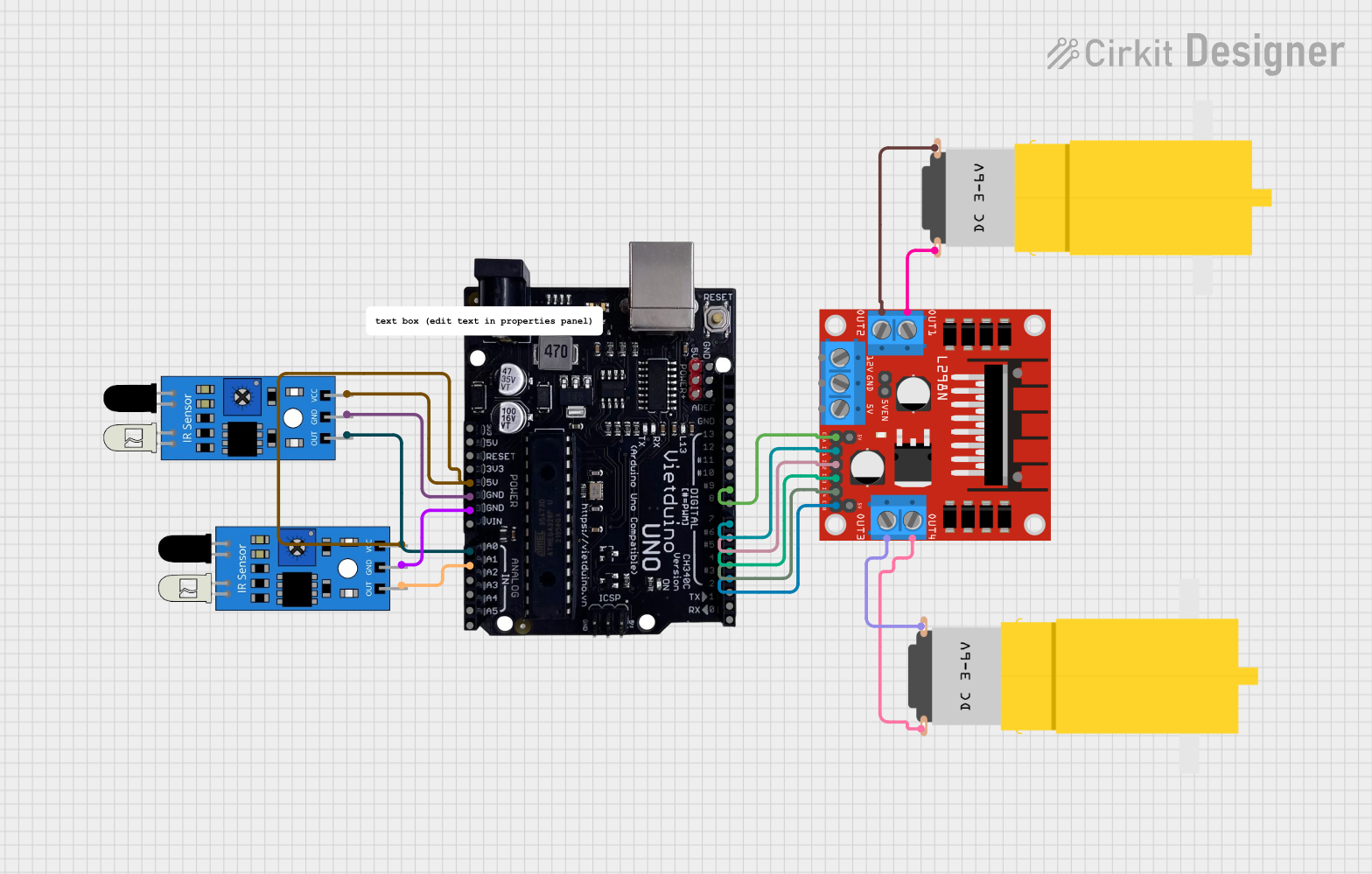
- Logic Control: Use a microcontroller (e.g., Arduino UNO) to control the INA1, INA2, INB1, INB2, PWM_A, and PWM_B pins. These pins determine the direction and speed of the motors.
- Enable Pins: Ensure the EN_A and EN_B pins are set high to enable motor operation.
- Current Sensing (Optional): If needed, connect the CS_A and CS_B pins to an analog input on your microcontroller to monitor motor current.
Important Considerations and Best Practices
- Heat Dissipation: The driver can handle high currents, but it may generate significant heat. Use a heatsink or active cooling to prevent thermal shutdown.
- Power Supply: Ensure your power supply can provide sufficient current for the motors and the driver.
- PWM Frequency: Use a PWM frequency of up to 20 kHz for optimal performance.
- Protection Features: The driver includes overcurrent and thermal protection, but avoid prolonged operation near its maximum ratings to ensure longevity.
Example Code for Arduino UNO
Below is an example of how to control a single motor using the Monster Motor Driver VNH2SP30 with an Arduino UNO:
// Define motor control pins
const int INA1 = 7;  // Motor A direction control pin 1
const int INA2 = 8;  // Motor A direction control pin 2
const int PWM_A = 9; // Motor A speed control (PWM) pin
const int EN_A = 10; // Motor A enable pin

void setup() {
  // Set motor control pins as outputs
  pinMode(INA1, OUTPUT);
  pinMode(INA2, OUTPUT);
  pinMode(PWM_A, OUTPUT);
  pinMode(EN_A, OUTPUT);

  // Enable motor A
  digitalWrite(EN_A, HIGH);
}

void loop() {
  // Rotate motor A forward at 50% speed
  digitalWrite(INA1, HIGH);
  digitalWrite(INA2, LOW);
  analogWrite(PWM_A, 128); // 50% duty cycle (128 out of 255)
  delay(2000); // Run for 2 seconds

  // Rotate motor A backward at 75% speed
  digitalWrite(INA1, LOW);
  digitalWrite(INA2, HIGH);
  analogWrite(PWM_A, 192); // 75% duty cycle (192 out of 255)
  delay(2000); // Run for 2 seconds

  // Stop motor A
  digitalWrite(INA1, LOW);
  digitalWrite(INA2, LOW);
  analogWrite(PWM_A, 0); // 0% duty cycle (motor off)
  delay(2000); // Wait for 2 seconds
}
Troubleshooting and FAQs
Common Issues and Solutions
Motor Not Running:
- Ensure the EN_A or EN_B pin is set high to enable the motor.
- Verify that the power supply voltage and current meet the motor's requirements.
- Check the wiring of the motor and control pins.
Driver Overheating:
- Use a heatsink or active cooling to dissipate heat.
- Reduce the motor load or operating current if possible.
Erratic Motor Behavior:
- Ensure proper grounding between the motor driver, power supply, and microcontroller.
- Verify that the PWM frequency is within the recommended range (up to 20 kHz).
No Current Sensing Output:
- Ensure the CS_A or CS_B pin is connected to an analog input on the microcontroller.
- Check the motor load; very low currents may not produce a noticeable signal.
FAQs
Q: Can I use this driver with a 24V motor?
A: No, the maximum operating voltage for the Monster Motor Driver VNH2SP30 is 16V. Using a higher voltage may damage the driver.
Q: Can I control two motors independently?
A: Yes, the driver has separate control pins for motor A and motor B, allowing independent control of two motors.
Q: What happens if the motor stalls?
A: The driver includes overcurrent protection, which will shut down the output to prevent damage. Reduce the load or check for obstructions in the motor.
Q: Can I use this driver with a stepper motor?
A: Yes, the driver can control a stepper motor by configuring the two H-bridges appropriately. However, additional logic may be required for precise stepper motor control.