How to Use wireless power transmitter coil: Examples, Pinouts, and Specs
Introduction
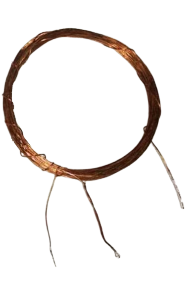
The Wireless Power Transmitter Coil (Manufacturer Part ID: transmitter coil in series 15-15 turns with center) is a key component in wireless power transfer systems. It is designed to generate an electromagnetic field that transfers energy to a compatible receiver coil without requiring physical connections. This coil is commonly used in applications such as wireless charging pads, contactless power delivery systems, and inductive coupling circuits.
Explore Projects Built with wireless power transmitter coil


Explore Projects Built with wireless power transmitter coil
Common Applications:
- Wireless charging for smartphones, wearables, and other portable devices
- Inductive power transfer for medical implants
- Contactless energy transfer in industrial automation
- Wireless power systems for IoT devices
Technical Specifications
Below are the key technical details for the Wireless Power Transmitter Coil:
| Parameter | Value |
|---|---|
| Manufacturer | DIY |
| Part ID | transmitter coil in series 15-15 turns with center |
| Coil Type | Series wound with center tap |
| Number of Turns | 15 turns per side (30 total) |
| Inductance | ~10 µH (typical, varies with load) |
| Operating Frequency | 100 kHz – 500 kHz |
| Maximum Current | 2 A |
| Maximum Voltage | 20 V |
| Core Material | Air core |
| Wire Gauge | 26 AWG |
| Dimensions | Outer Diameter: 50 mm, Thickness: 5 mm |
Pin Configuration and Descriptions
The transmitter coil has three connection points due to its center-tapped design. The pin configuration is as follows:
| Pin | Description |
|---|---|
| Pin 1 | Start of the first winding (primary side) |
| Pin 2 | Center tap (common connection for both windings) |
| Pin 3 | End of the second winding (secondary side) |
Usage Instructions
How to Use the Component in a Circuit
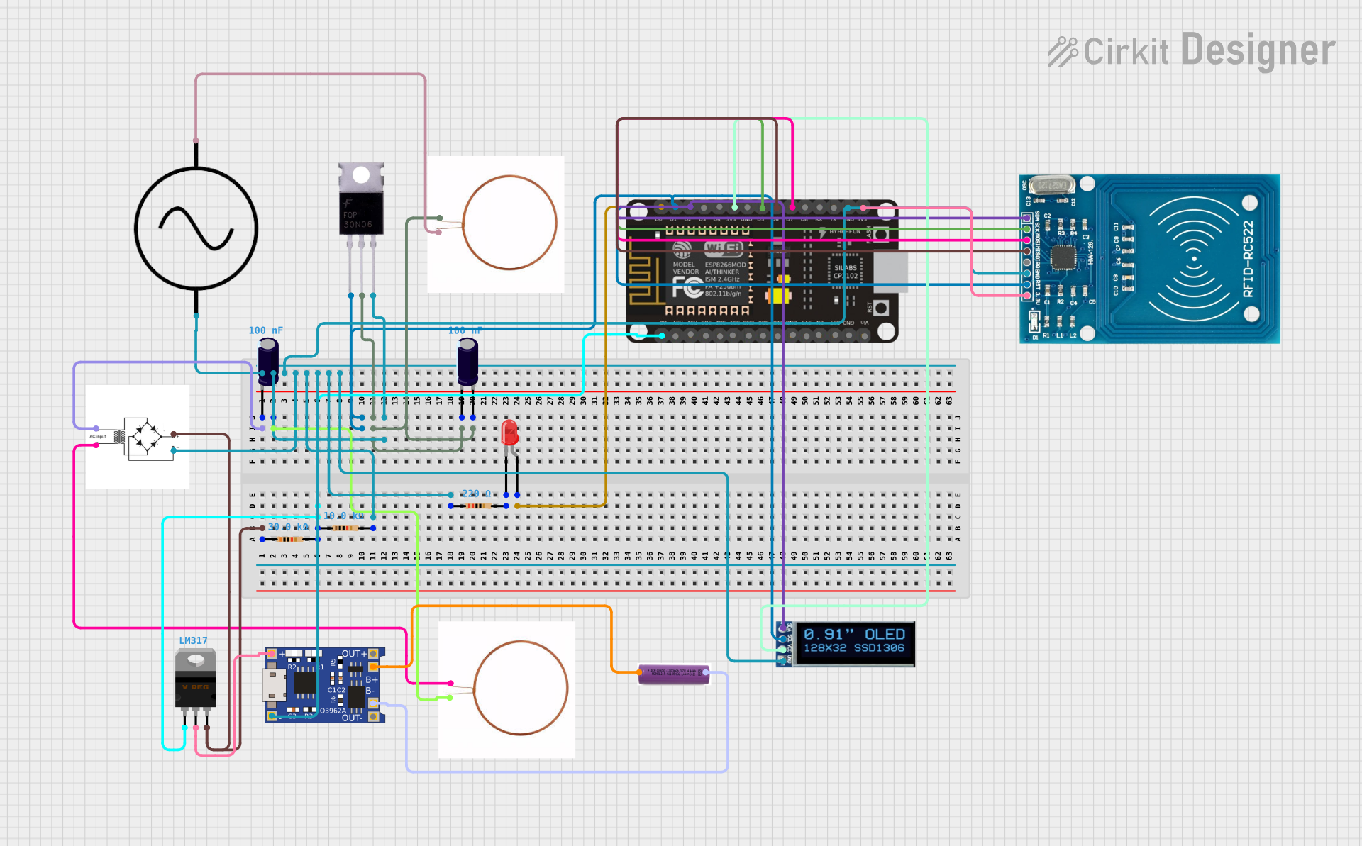
- Power Supply: Connect the transmitter coil to a high-frequency AC power source (e.g., a resonant circuit or an H-bridge driver) operating within the specified frequency range (100 kHz – 500 kHz).
- Center Tap: Use the center tap (Pin 2) as a common ground or reference point, depending on your circuit design.
- Receiver Coil: Place a compatible receiver coil within the electromagnetic field generated by the transmitter coil. Ensure proper alignment for maximum energy transfer efficiency.
- Load Matching: Use capacitors to create a resonant LC circuit with the coil. This improves efficiency by matching the load impedance to the transmitter coil.
Important Considerations and Best Practices
- Alignment: Ensure the transmitter and receiver coils are aligned and positioned at the correct distance for optimal power transfer.
- Resonance Tuning: Use a capacitor in parallel with the coil to tune the circuit to the desired operating frequency.
- Heat Management: Avoid exceeding the maximum current rating (2 A) to prevent overheating.
- Interference: Minimize electromagnetic interference by shielding nearby sensitive components or circuits.
- Testing: Use an oscilloscope to verify the waveform and frequency of the AC signal driving the coil.
Example: Using the Coil with an Arduino UNO
Below is an example of how to drive the transmitter coil using an Arduino UNO and an H-bridge driver circuit:
/*
 * Example: Driving a Wireless Power Transmitter Coil with Arduino UNO
 * This code generates a PWM signal to drive an H-bridge circuit, which powers
 * the transmitter coil. Adjust the frequency and duty cycle as needed.
 */

const int pwmPin = 9; // PWM output pin connected to H-bridge input

void setup() {
  pinMode(pwmPin, OUTPUT);

  // Set up PWM frequency and duty cycle
  // Arduino default PWM frequency on pin 9 is ~490 Hz. Use Timer1 for higher freq.
  TCCR1A = 0b10100010; // Fast PWM mode, non-inverted output
  TCCR1B = 0b00011001; // Prescaler = 1, Fast PWM mode
  ICR1 = 159;          // Set TOP value for ~100 kHz frequency
  OCR1A = 80;          // Set duty cycle to 50% (adjust as needed)
}

void loop() {
  // The PWM signal is continuously generated by hardware timers
}
Note: Ensure the H-bridge driver circuit is capable of handling the required voltage and current for the transmitter coil.
Troubleshooting and FAQs
Common Issues and Solutions
No Power Transfer to Receiver Coil
- Cause: Misalignment between transmitter and receiver coils.
- Solution: Adjust the position and alignment of the coils for better coupling.
Overheating of the Coil
- Cause: Exceeding the maximum current rating or poor resonance tuning.
- Solution: Verify the current draw and ensure proper resonance tuning with a capacitor.
Low Efficiency
- Cause: Incorrect operating frequency or poor impedance matching.
- Solution: Use an oscilloscope to verify the operating frequency and adjust the capacitor value for resonance.
Interference with Nearby Electronics
- Cause: Electromagnetic interference (EMI) from the coil.
- Solution: Add shielding or increase the distance between the coil and sensitive components.
FAQs
Q1: Can this coil be used for high-power applications?
A1: No, this coil is designed for low to medium power applications with a maximum current of 2 A and voltage of 20 V.
Q2: How do I calculate the resonant capacitor value?
A2: Use the formula ( C = \frac{1}{(2 \pi f)^2 L} ), where ( f ) is the operating frequency and ( L ) is the inductance of the coil.
Q3: Can I use this coil with a DC power source?
A3: No, the coil requires a high-frequency AC signal to generate the electromagnetic field.
Q4: What is the recommended distance between the transmitter and receiver coils?
A4: The optimal distance depends on the application but is typically within a few millimeters to a few centimeters.
By following this documentation, you can effectively integrate the Wireless Power Transmitter Coil into your wireless power transfer projects.