How to Use Orange Pi 1: Examples, Pinouts, and Specs
Introduction
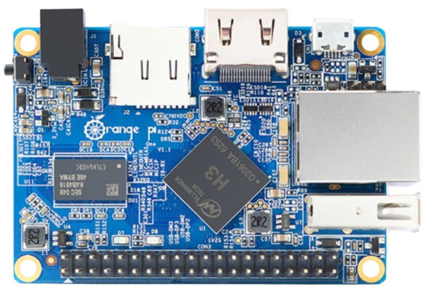
The Orange Pi 1 is a compact and affordable single-board computer (SBC) powered by an ARM Cortex-A7 processor. It is designed to provide a versatile platform for a wide range of computing tasks, including media playback, gaming, IoT applications, and educational projects. With support for multiple operating systems such as Linux and Android, the Orange Pi 1 is a flexible choice for developers, hobbyists, and students. Additionally, its GPIO pins enable hardware interfacing, making it suitable for embedded systems and hardware prototyping.
Explore Projects Built with Orange Pi 1
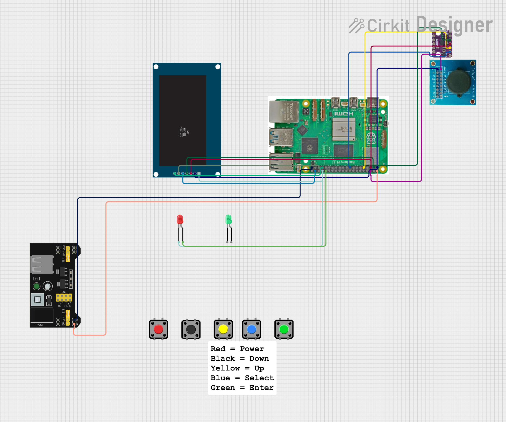


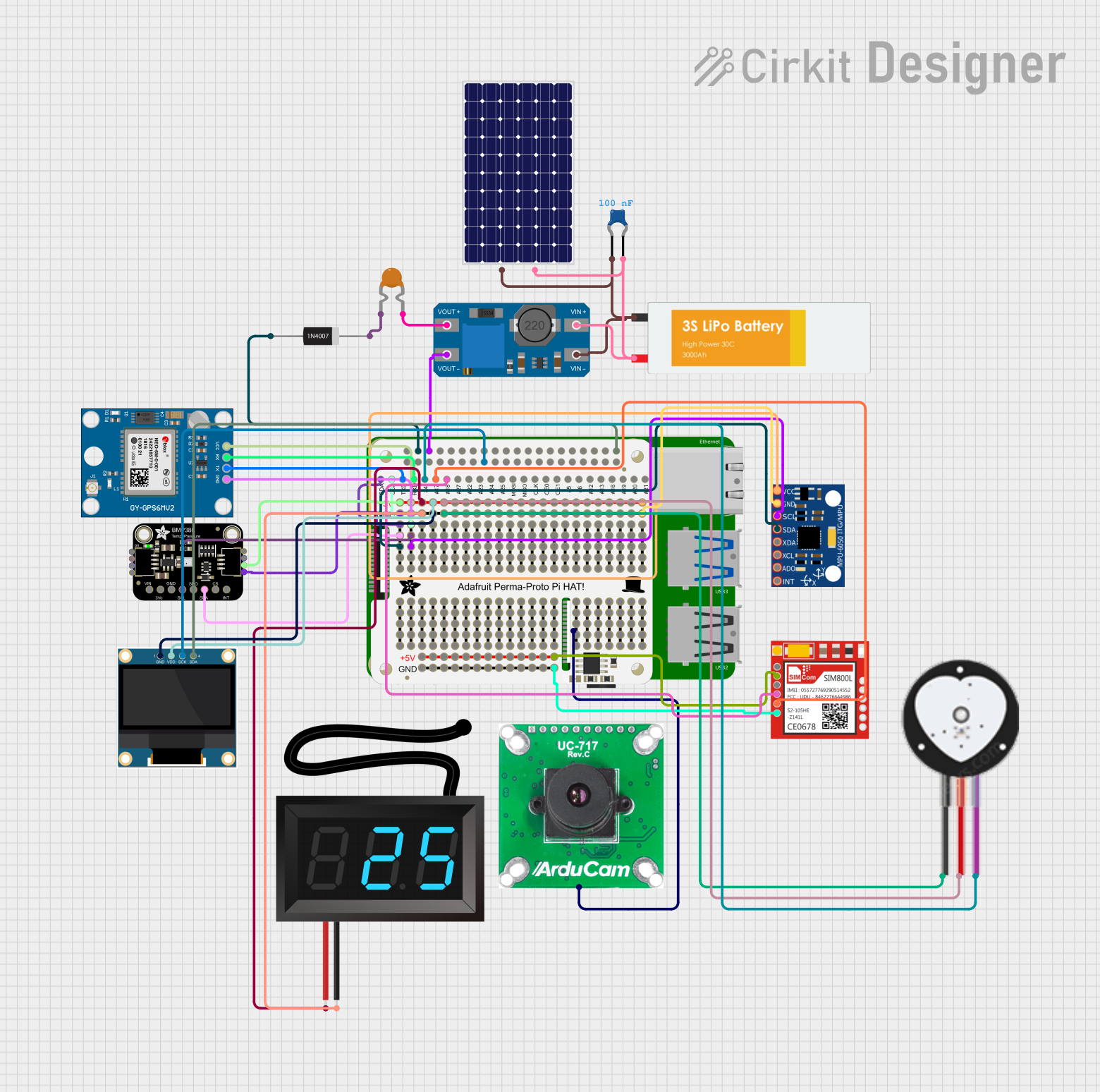
Explore Projects Built with Orange Pi 1
Common Applications and Use Cases
- Media centers and home entertainment systems
- IoT devices and smart home automation
- Educational tools for learning programming and electronics
- Lightweight servers and network applications
- Robotics and hardware prototyping
Technical Specifications
The Orange Pi 1 offers a robust set of features for its size and price. Below are the key technical details:
General Specifications
| Feature | Specification |
|---|---|
| Processor | Allwinner H3 Quad-core ARM Cortex-A7 |
| GPU | Mali-400 MP2 |
| RAM | 512MB DDR3 |
| Storage | microSD card slot, up to 32GB |
| Operating System Support | Android, Debian, Ubuntu, Armbian |
| Connectivity | 10/100 Ethernet, USB 2.0 ports (x2) |
| Video Output | HDMI, Composite Video |
| Audio Output | HDMI, 3.5mm audio jack |
| GPIO Pins | 26-pin header (compatible with Raspberry Pi) |
GPIO Pin Configuration
The Orange Pi 1 features a 26-pin GPIO header for hardware interfacing. Below is the pinout:
| Pin Number | Pin Name | Description |
|---|---|---|
| 1 | 3.3V | Power supply (3.3V) |
| 2 | 5V | Power supply (5V) |
| 3 | GPIO2 (SDA) | I2C Data |
| 4 | 5V | Power supply (5V) |
| 5 | GPIO3 (SCL) | I2C Clock |
| 6 | GND | Ground |
| 7 | GPIO4 | General-purpose I/O |
| 8 | GPIO14 (TXD) | UART Transmit |
| 9 | GND | Ground |
| 10 | GPIO15 (RXD) | UART Receive |
| 11 | GPIO17 | General-purpose I/O |
| 12 | GPIO18 | PWM Output |
| 13 | GPIO27 | General-purpose I/O |
| 14 | GND | Ground |
| 15 | GPIO22 | General-purpose I/O |
| 16 | GPIO23 | General-purpose I/O |
| 17 | 3.3V | Power supply (3.3V) |
| 18 | GPIO24 | General-purpose I/O |
| 19 | GPIO10 (MOSI) | SPI Master Out, Slave In |
| 20 | GND | Ground |
| 21 | GPIO9 (MISO) | SPI Master In, Slave Out |
| 22 | GPIO25 | General-purpose I/O |
| 23 | GPIO11 (SCLK) | SPI Clock |
| 24 | GPIO8 (CE0) | SPI Chip Enable 0 |
| 25 | GND | Ground |
| 26 | GPIO7 (CE1) | SPI Chip Enable 1 |
Usage Instructions
The Orange Pi 1 can be used in a variety of projects, from running a media server to controlling hardware via GPIO. Below are the steps to get started:
Setting Up the Orange Pi 1
- Prepare the Operating System:
- Download a compatible OS image (e.g., Armbian, Ubuntu, or Android) from the official Orange Pi website or community forums.
- Use a tool like Balena Etcher to flash the OS image onto a microSD card.
- Connect Peripherals:
- Insert the microSD card into the Orange Pi 1.
- Connect an HDMI cable to a monitor or TV.
- Attach a USB keyboard and mouse.
- Optionally, connect an Ethernet cable for network access.
- Power On:
- Connect a 5V/2A power supply to the Orange Pi 1.
- The board will boot into the operating system.
Using GPIO Pins
The GPIO pins on the Orange Pi 1 can be used to interface with external hardware such as LEDs, sensors, and motors. Below is an example of controlling an LED using Python:
Example: Blinking an LED
Connect the LED:
- Connect the positive leg of the LED to GPIO17 (Pin 11).
- Connect the negative leg of the LED to a 330-ohm resistor, and then to GND (Pin 14).
Install Required Libraries:
- Install the
RPi.GPIOlibrary (compatible with Orange Pi) using the following command:sudo apt-get install python3-rpi.gpio
- Install the
Write the Code: Save the following Python code to a file (e.g.,
blink.py):import RPi.GPIO as GPIO # Import GPIO library import time # Import time library for delays # Pin configuration LED_PIN = 11 # GPIO17 corresponds to Pin 11 on the header # GPIO setup GPIO.setmode(GPIO.BOARD) # Use physical pin numbering GPIO.setup(LED_PIN, GPIO.OUT) # Set pin as output try: while True: GPIO.output(LED_PIN, GPIO.HIGH) # Turn LED on time.sleep(1) # Wait for 1 second GPIO.output(LED_PIN, GPIO.LOW) # Turn LED off time.sleep(1) # Wait for 1 second except KeyboardInterrupt: GPIO.cleanup() # Clean up GPIO settings on exitRun the Code: Execute the script using:
python3 blink.py
Important Considerations
- Use a reliable 5V/2A power supply to ensure stable operation.
- Avoid shorting GPIO pins to prevent damage to the board.
- Always shut down the operating system properly before disconnecting power.
Troubleshooting and FAQs
Common Issues
The board does not boot:
- Ensure the microSD card is properly inserted.
- Verify that the OS image was flashed correctly.
- Check the power supply for sufficient voltage and current.
No display on the monitor:
- Confirm the HDMI cable is securely connected.
- Try a different monitor or HDMI cable.
- Ensure the OS image supports HDMI output.
GPIO pins not working:
- Verify the pin configuration in your code.
- Check for loose connections in the circuit.
- Ensure the
RPI.GPIOlibrary is installed and configured correctly.
FAQs
Can I use the Orange Pi 1 with a Raspberry Pi HAT?
- Yes, the GPIO header is compatible with most Raspberry Pi HATs, but software support may vary.
What is the maximum supported microSD card size?
- The Orange Pi 1 supports microSD cards up to 32GB.
Can I power the board via GPIO pins?
- Yes, you can supply 5V to the 5V pin, but ensure the power source is stable and regulated.
Is Wi-Fi supported?
- The Orange Pi 1 does not have built-in Wi-Fi, but you can use a USB Wi-Fi adapter.
By following this documentation, you can effectively utilize the Orange Pi 1 for a variety of projects and applications.