Cirkit Designer Logo
Cirkit Designer
Your all-in-one circuit design IDE
Home / 
Component Documentation

How to Use TTL TO 485: Examples, Pinouts, and Specs

Image of TTL TO 485
Cirkit Designer LogoDesign with TTL TO 485 in Cirkit Designer

Introduction

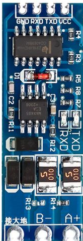
The TTL to RS-485 converter is an electronic module designed to convert TTL-level signals (typically 0–5V or 0–3.3V) into RS-485 differential signals. RS-485 is a robust communication standard widely used for long-distance and noise-resistant data transmission in industrial and embedded systems. This module enables seamless communication between TTL-based devices, such as microcontrollers, and RS-485 networks.

Explore Projects Built with TTL TO 485

Use Cirkit Designer to design, explore, and prototype these projects online. Some projects support real-time simulation. Click "Open Project" to start designing instantly!
Arduino UNO and Relay-Controlled RS485 Communication System
Image of Diagrama: A project utilizing TTL TO 485 in a practical application
This circuit features an Arduino UNO microcontroller interfaced with a 4-channel relay module and a UART TTL to RS485 converter. The Arduino controls the relays via digital pins and communicates with the RS485 converter for serial communication, enabling control of external devices and communication over long distances.
Cirkit Designer LogoOpen Project in Cirkit Designer
RS485-Enabled NPK Soil Sensor Interface
Image of NPK: A project utilizing TTL TO 485 in a practical application
This circuit connects an NPK Soil Sensor to an RS485 transceiver module. The sensor's VCC and GND pins are connected to the corresponding VCC and GND pins on the RS485 module to provide power. The sensor's analog output (A) and digital output (B) are interfaced with the RS485 module's DI (Data Input) and DE (Driver Enable) pins, respectively, allowing the sensor's signals to be transmitted over an RS485 communication bus.
Cirkit Designer LogoOpen Project in Cirkit Designer
STM32 and Arduino UNO Based Dual RS485 Communication Interface
Image of STM to Arduino RS485: A project utilizing TTL TO 485 in a practical application
This circuit consists of two microcontrollers, an STM32F103C8T6 and an Arduino UNO, each interfaced with separate RS485 transceiver modules for serial communication. The STM32F103C8T6 controls the RE (Receiver Enable) and DE (Driver Enable) pins of one RS485 module to manage its operation, and communicates via the A9 and A10 pins for DI (Data Input) and RO (Receiver Output), respectively. The Arduino UNO is similarly connected to another RS485 module, with digital pins D2 and D3 interfacing with DI and RO, and D8 controlling both RE and DE. The RS485 modules are connected to each other through their A and B differential communication lines, enabling serial data exchange between the two microcontrollers over a robust and long-distance capable RS485 network.
Cirkit Designer LogoOpen Project in Cirkit Designer
ESP32C3-Based Soil Monitoring System with RS485 Communication
Image of 3-slave-soil: A project utilizing TTL TO 485 in a practical application
This circuit features an ESP32C3 Supermini microcontroller interfaced with an RS485 transceiver module, allowing for serial communication over long distances. A toggle switch and a pushbutton are connected to the ESP32C3 for user input, with a pull-up resistor on the toggle switch. Additionally, the circuit includes an NPK Soil Sensor connected to the RS485 module for measuring soil nutrient levels, with power supplied to the sensor and RS485 module from the ESP32C3.
Cirkit Designer LogoOpen Project in Cirkit Designer

Explore Projects Built with TTL TO 485

Use Cirkit Designer to design, explore, and prototype these projects online. Some projects support real-time simulation. Click "Open Project" to start designing instantly!
Image of Diagrama: A project utilizing TTL TO 485 in a practical application
Arduino UNO and Relay-Controlled RS485 Communication System
This circuit features an Arduino UNO microcontroller interfaced with a 4-channel relay module and a UART TTL to RS485 converter. The Arduino controls the relays via digital pins and communicates with the RS485 converter for serial communication, enabling control of external devices and communication over long distances.
Cirkit Designer LogoOpen Project in Cirkit Designer
Image of NPK: A project utilizing TTL TO 485 in a practical application
RS485-Enabled NPK Soil Sensor Interface
This circuit connects an NPK Soil Sensor to an RS485 transceiver module. The sensor's VCC and GND pins are connected to the corresponding VCC and GND pins on the RS485 module to provide power. The sensor's analog output (A) and digital output (B) are interfaced with the RS485 module's DI (Data Input) and DE (Driver Enable) pins, respectively, allowing the sensor's signals to be transmitted over an RS485 communication bus.
Cirkit Designer LogoOpen Project in Cirkit Designer
Image of STM to Arduino RS485: A project utilizing TTL TO 485 in a practical application
STM32 and Arduino UNO Based Dual RS485 Communication Interface
This circuit consists of two microcontrollers, an STM32F103C8T6 and an Arduino UNO, each interfaced with separate RS485 transceiver modules for serial communication. The STM32F103C8T6 controls the RE (Receiver Enable) and DE (Driver Enable) pins of one RS485 module to manage its operation, and communicates via the A9 and A10 pins for DI (Data Input) and RO (Receiver Output), respectively. The Arduino UNO is similarly connected to another RS485 module, with digital pins D2 and D3 interfacing with DI and RO, and D8 controlling both RE and DE. The RS485 modules are connected to each other through their A and B differential communication lines, enabling serial data exchange between the two microcontrollers over a robust and long-distance capable RS485 network.
Cirkit Designer LogoOpen Project in Cirkit Designer
Image of 3-slave-soil: A project utilizing TTL TO 485 in a practical application
ESP32C3-Based Soil Monitoring System with RS485 Communication
This circuit features an ESP32C3 Supermini microcontroller interfaced with an RS485 transceiver module, allowing for serial communication over long distances. A toggle switch and a pushbutton are connected to the ESP32C3 for user input, with a pull-up resistor on the toggle switch. Additionally, the circuit includes an NPK Soil Sensor connected to the RS485 module for measuring soil nutrient levels, with power supplied to the sensor and RS485 module from the ESP32C3.
Cirkit Designer LogoOpen Project in Cirkit Designer

Common Applications and Use Cases

  • Industrial automation and control systems
  • Long-distance communication between microcontrollers or sensors
  • RS-485-based protocols like Modbus
  • Home automation systems
  • Data acquisition systems

Technical Specifications

Below are the key technical details of the TTL to RS-485 converter:

Parameter Value
Operating Voltage 3.3V or 5V
Communication Standard RS-485
Baud Rate Up to 115200 bps
Operating Temperature -40°C to 85°C
Maximum Communication Distance Up to 1200 meters (4000 feet)
Input Signal Level TTL (0–5V or 0–3.3V)
Output Signal Level RS-485 differential
Power Consumption Low power consumption

Pin Configuration and Descriptions

The TTL to RS-485 converter typically has the following pinout:

Pin Name Description
VCC Power supply input (3.3V or 5V, depending on the module)
GND Ground connection
TXD TTL-level transmit data input (from microcontroller or TTL device)
RXD TTL-level receive data output (to microcontroller or TTL device)
A (D+) RS-485 differential signal positive terminal
B (D-) RS-485 differential signal negative terminal
DE Driver enable pin (active high, controls RS-485 driver mode)
RE Receiver enable pin (active low, controls RS-485 receiver mode)

Usage Instructions

How to Use the Component in a Circuit

  1. Power the Module: Connect the VCC pin to a 3.3V or 5V power source and the GND pin to the ground.
  2. Connect TTL Signals:
    • Connect the TXD pin of the module to the TX pin of your microcontroller.
    • Connect the RXD pin of the module to the RX pin of your microcontroller.
  3. Connect RS-485 Signals:
    • Connect the A (D+) and B (D-) pins to the RS-485 bus.
    • Ensure proper termination resistors (typically 120Ω) are used at both ends of the RS-485 bus for signal integrity.
  4. Control DE and RE Pins:
    • Tie DE and RE together for automatic control or manage them separately using GPIO pins.
    • Set DE high to enable transmission and RE low to enable reception.

Important Considerations and Best Practices

  • Voltage Compatibility: Ensure the module's operating voltage matches your microcontroller's logic level (3.3V or 5V).
  • Termination Resistors: Use 120Ω termination resistors at both ends of the RS-485 bus to prevent signal reflections.
  • Biasing Resistors: Add pull-up and pull-down resistors on the A and B lines to maintain a known idle state.
  • Grounding: Connect the GND of the module to the GND of the microcontroller and RS-485 network for proper signal reference.
  • Cable Selection: Use twisted-pair cables for RS-485 communication to minimize noise and interference.

Example: Connecting to an Arduino UNO

Below is an example of how to use the TTL to RS-485 converter with an Arduino UNO for communication:
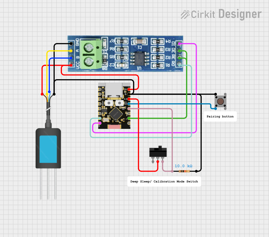
Circuit Diagram

  • Connect the VCC and GND pins of the module to the 5V and GND pins of the Arduino.
  • Connect the TXD pin of the module to the Arduino's TX (D1) pin.
  • Connect the RXD pin of the module to the Arduino's RX (D0) pin.
  • Connect the A and B pins to the RS-485 bus.

Arduino Code Example

// Example code for using TTL to RS-485 converter with Arduino UNO
// This code sends "Hello, RS-485!" over the RS-485 bus.

void setup() {
  Serial.begin(9600); // Initialize serial communication at 9600 baud
  delay(1000);        // Wait for the module to initialize
}

void loop() {
  Serial.println("Hello, RS-485!"); // Send data over RS-485
  delay(1000);                      // Wait 1 second before sending again
}

Troubleshooting and FAQs

Common Issues and Solutions

  1. No Communication on RS-485 Bus:

    • Cause: Incorrect wiring or missing termination resistors.
    • Solution: Double-check all connections and ensure 120Ω termination resistors are installed at both ends of the RS-485 bus.
  2. Data Corruption or Noise:

    • Cause: Long cables or improper grounding.
    • Solution: Use twisted-pair cables, ensure proper grounding, and verify that the cable length is within the RS-485 standard limits.
  3. Module Not Powering On:

    • Cause: Incorrect power supply voltage.
    • Solution: Verify that the VCC pin is connected to a 3.3V or 5V power source.
  4. DE/RE Pins Not Configured Properly:

    • Cause: DE and RE pins not controlled correctly.
    • Solution: Tie DE high and RE low for transmission, or use GPIO pins to control them dynamically.

FAQs

Q1: Can I use this module with a 3.3V microcontroller?
A1: Yes, the module supports both 3.3V and 5V logic levels. Ensure the VCC pin is connected to the appropriate voltage.

Q2: What is the maximum baud rate supported?
A2: The module supports baud rates up to 115200 bps, but the actual performance may depend on cable length and environmental noise.

Q3: Do I need to use termination resistors?
A3: Yes, termination resistors (120Ω) are essential for maintaining signal integrity on the RS-485 bus.

Q4: Can I connect multiple devices to the RS-485 bus?
A4: Yes, RS-485 supports multi-drop communication with up to 32 devices on the same bus.

By following this documentation, you can effectively integrate the TTL to RS-485 converter into your projects for reliable long-distance communication.