Cirkit Designer Logo
Cirkit Designer
Your all-in-one circuit design IDE
Home / 
Component Documentation

How to Use PZEM004t: Examples, Pinouts, and Specs

Image of PZEM004t
Cirkit Designer LogoDesign with PZEM004t in Cirkit Designer

Introduction

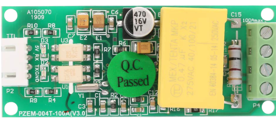
The PZEM004T is a versatile and highly accurate digital power meter designed to measure various electrical parameters including voltage, current, power, energy, and frequency. It is widely used in monitoring energy consumption for household appliances, industrial machinery, and various electronic projects. Its ability to interface with microcontrollers like the Arduino UNO makes it a popular choice for DIY enthusiasts and professionals looking to build energy monitoring systems.

Explore Projects Built with PZEM004t

Use Cirkit Designer to design, explore, and prototype these projects online. Some projects support real-time simulation. Click "Open Project" to start designing instantly!
ESP32-Based Smart Environmental Monitoring System with Relay Control
Image of SOCOTECO: A project utilizing PZEM004t in a practical application
This is a smart environmental monitoring and control system featuring an ESP32 microcontroller interfaced with a PZEM004T for power monitoring, relay modules for actuating bulbs and a fan, and an LCD for user interface. It includes flame, gas, and vibration sensors for safety monitoring purposes.
Cirkit Designer LogoOpen Project in Cirkit Designer
ESP32-Controlled AC Lighting System with Power Monitoring
Image of Smart Energy Meter: A project utilizing PZEM004t in a practical application
This circuit features an ESP32 microcontroller interfaced with a PZEM004T power monitoring module and a 4-channel relay module controlling multiple AC LED bulbs. The ESP32 uses GPIO pins to control the relays, which in turn switch the LED bulbs on and off. The PZEM004T is connected to the ESP32 for communication and to a current sensor for monitoring power consumption of the connected load through the relay contacts.
Cirkit Designer LogoOpen Project in Cirkit Designer
ESP32-Based Smart Energy Monitoring and Control System with PZEM004t and LCD Display
Image of pr1: A project utilizing PZEM004t in a practical application
This circuit is a monitoring and control system using an ESP32 microcontroller. It integrates multiple PZEM004t energy meters, a rain gauge, a light sensor, and an LCD display for data visualization. Additionally, it controls a relay module to switch a bulb on or off based on sensor inputs.
Cirkit Designer LogoOpen Project in Cirkit Designer
ESP32-Based Smart Power Monitoring and Control System with Wi-Fi Connectivity
Image of SIM: A project utilizing PZEM004t in a practical application
This circuit is a smart power monitoring and control system using an ESP32 microcontroller. It features multiple sensors and components, including PZEM-004T AC modules for voltage and current measurement, DS18B20 temperature sensors, an LCD for display, and solid-state relays for controlling power outlets. The system is integrated with Blynk for remote monitoring and control, and includes pushbuttons for local interaction.
Cirkit Designer LogoOpen Project in Cirkit Designer

Explore Projects Built with PZEM004t

Use Cirkit Designer to design, explore, and prototype these projects online. Some projects support real-time simulation. Click "Open Project" to start designing instantly!
Image of SOCOTECO: A project utilizing PZEM004t in a practical application
ESP32-Based Smart Environmental Monitoring System with Relay Control
This is a smart environmental monitoring and control system featuring an ESP32 microcontroller interfaced with a PZEM004T for power monitoring, relay modules for actuating bulbs and a fan, and an LCD for user interface. It includes flame, gas, and vibration sensors for safety monitoring purposes.
Cirkit Designer LogoOpen Project in Cirkit Designer
Image of Smart Energy Meter: A project utilizing PZEM004t in a practical application
ESP32-Controlled AC Lighting System with Power Monitoring
This circuit features an ESP32 microcontroller interfaced with a PZEM004T power monitoring module and a 4-channel relay module controlling multiple AC LED bulbs. The ESP32 uses GPIO pins to control the relays, which in turn switch the LED bulbs on and off. The PZEM004T is connected to the ESP32 for communication and to a current sensor for monitoring power consumption of the connected load through the relay contacts.
Cirkit Designer LogoOpen Project in Cirkit Designer
Image of pr1: A project utilizing PZEM004t in a practical application
ESP32-Based Smart Energy Monitoring and Control System with PZEM004t and LCD Display
This circuit is a monitoring and control system using an ESP32 microcontroller. It integrates multiple PZEM004t energy meters, a rain gauge, a light sensor, and an LCD display for data visualization. Additionally, it controls a relay module to switch a bulb on or off based on sensor inputs.
Cirkit Designer LogoOpen Project in Cirkit Designer
Image of SIM: A project utilizing PZEM004t in a practical application
ESP32-Based Smart Power Monitoring and Control System with Wi-Fi Connectivity
This circuit is a smart power monitoring and control system using an ESP32 microcontroller. It features multiple sensors and components, including PZEM-004T AC modules for voltage and current measurement, DS18B20 temperature sensors, an LCD for display, and solid-state relays for controlling power outlets. The system is integrated with Blynk for remote monitoring and control, and includes pushbuttons for local interaction.
Cirkit Designer LogoOpen Project in Cirkit Designer

Common Applications and Use Cases

  • Home energy monitoring systems
  • Industrial power management
  • Renewable energy systems (solar, wind, etc.)
  • Laboratory instruments for electrical measurements
  • IoT devices for smart energy solutions

Technical Specifications

Key Technical Details

  • Voltage Measurement Range: 80 - 260V AC
  • Current Measurement Range: 0 - 100A (with appropriate current transformer)
  • Power Measurement Range: 0 - 22kW
  • Energy Measurement Range: 0 - 9999kWh
  • Frequency Measurement Range: 45 - 65Hz
  • Measurement Accuracy: 1.0%

Pin Configuration and Descriptions

Pin Number Function Description
1 VCC Power supply input (5V DC)
2 GND Ground
3 RX Receive pin, used to receive data from the PZEM (TTL logic)
4 TX Transmit pin, used to send data to the PZEM (TTL logic)

Usage Instructions

How to Use the PZEM004T in a Circuit

  1. Power Supply: Connect the VCC pin to a 5V power source and the GND pin to the common ground.
  2. Current Transformer: Attach the current transformer around the live wire of the circuit you wish to measure.
  3. Voltage Measurement: Connect the voltage measurement terminals of the PZEM004T across the points in the circuit where you want to measure the voltage.
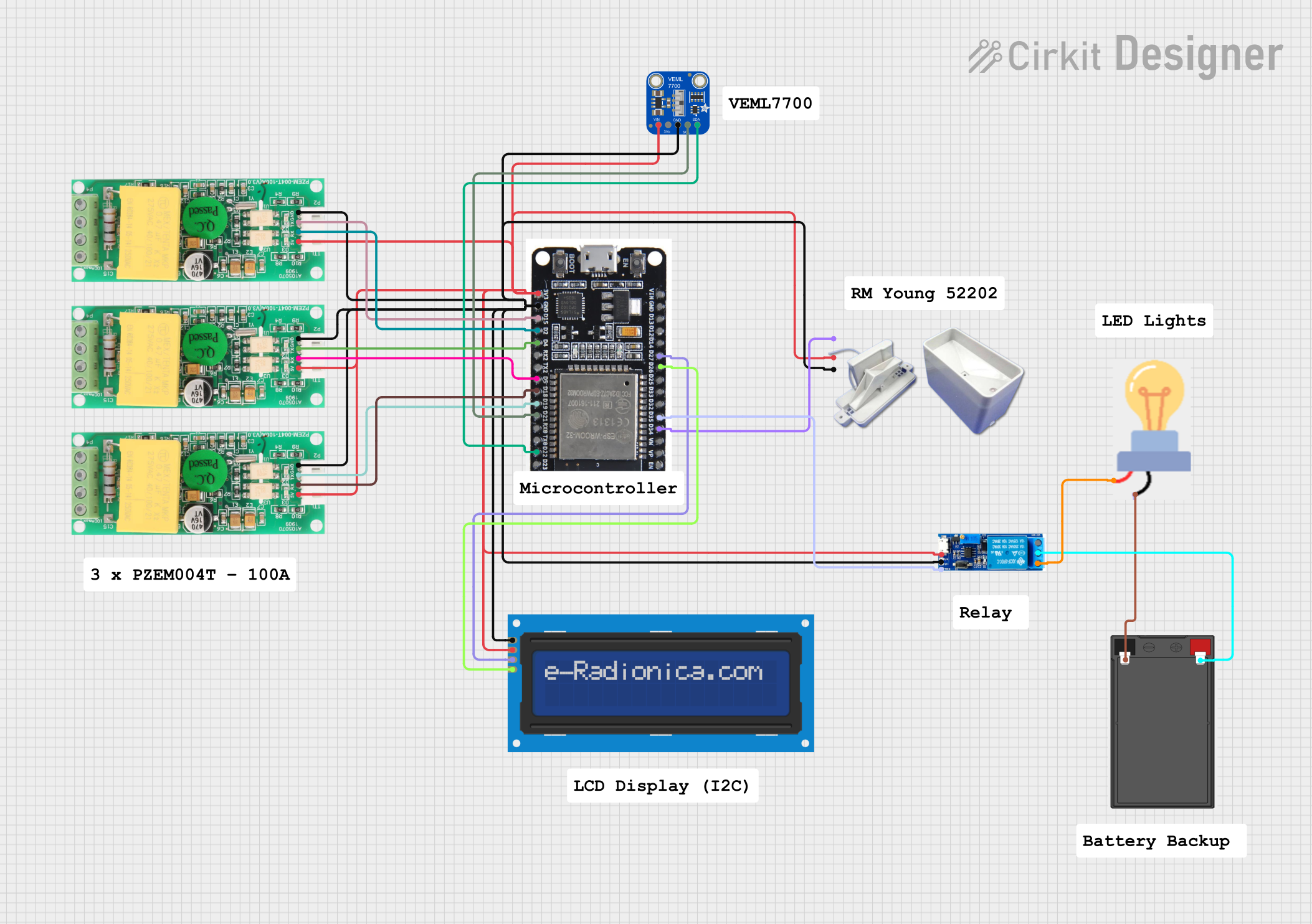
  4. Data Communication: Connect the RX and TX pins to a microcontroller or a computer to read the data from the PZEM004T.

Important Considerations and Best Practices

  • Ensure that the power supply to the PZEM004T does not exceed 5V DC.
  • Always disconnect the power before making any connections to avoid electric shock.
  • Use appropriate gauge wires for connections, especially for high current applications.
  • Do not exceed the maximum ratings of voltage and current specified by the manufacturer.
  • When using with a microcontroller, ensure proper level shifting if required (e.g., when using a 3.3V logic level microcontroller).

Troubleshooting and FAQs

Common Issues Users Might Face

  • No Data Output: Check connections to the RX and TX pins, and ensure the power supply is stable.
  • Inaccurate Readings: Verify that the current transformer is properly installed and that there are no loose connections.
  • Device Not Powering Up: Ensure that the VCC and GND connections are correct and that the power supply is within the specified range.

Solutions and Tips for Troubleshooting

  • Double-check wiring and solder joints for any potential issues.
  • Use a multimeter to verify the voltage at the VCC pin.
  • Ensure that the serial communication baud rate matches the PZEM004T's default baud rate.

FAQs

Q: Can the PZEM004T be used with an Arduino UNO? A: Yes, the PZEM004T can be easily connected to an Arduino UNO for data logging and monitoring.

Q: What is the default baud rate for the PZEM004T? A: The default baud rate for serial communication with the PZEM004T is 9600 bps.

Q: How can I reset the energy data on the PZEM004T? A: Energy data can be reset through a command sent from the microcontroller to the PZEM004T.

Example Arduino UNO Code

#include <SoftwareSerial.h> // Include the SoftwareSerial library

// PZEM004T connection pins
#define PZEM_RX 6
#define PZEM_TX 7

// Create a SoftwareSerial object
SoftwareSerial pzem(PZEM_RX, PZEM_TX);

void setup() {
  Serial.begin(9600); // Start the Serial communication
  pzem.begin(9600);  // Start the PZEM communication
}

void loop() {
  // Send request for data to PZEM004T
  pzem.write(0xB0);
  pzem.write(0xC0);
  pzem.write(0xA8);
  pzem.write(0x01);
  pzem.write(0x01);
  pzem.write(0x00);
  pzem.write(0x1E);

  // Wait for a response
  delay(1000);

  // Read the response and print it to the Serial Monitor
  if (pzem.available()) {
    Serial.print("Voltage: ");
    Serial.print(pzem.read()); // Read voltage
    Serial.println("V");

    // Repeat for current, power, energy, and frequency
    // ...
  }
}

Note: This example code is for demonstration purposes only and may require additional commands and error checking for practical applications. Always refer to the PZEM004T datasheet for detailed communication protocol information.