How to Use RPLiDAR A2M8-R3: Examples, Pinouts, and Specs
Introduction
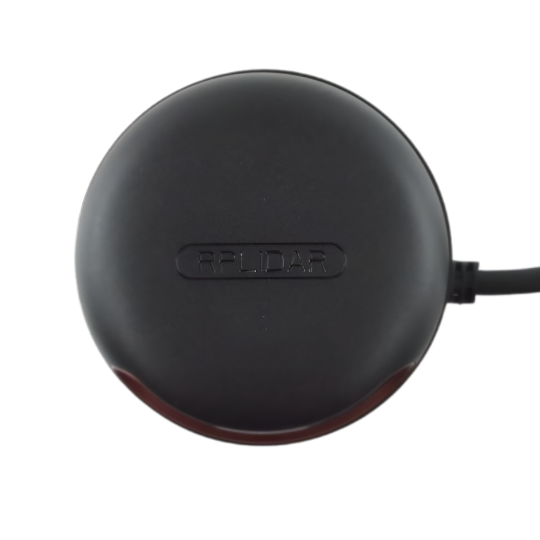
The RPLiDAR A2M8-R3 is a 360-degree laser scanner designed for mapping, navigation, and obstacle detection in robotics and automation systems. It provides high-resolution distance measurements by emitting laser pulses and analyzing their reflections. This compact and lightweight LiDAR sensor is capable of operating in various environments, making it ideal for applications such as autonomous robots, drones, SLAM (Simultaneous Localization and Mapping), and smart home devices.
Explore Projects Built with RPLiDAR A2M8-R3
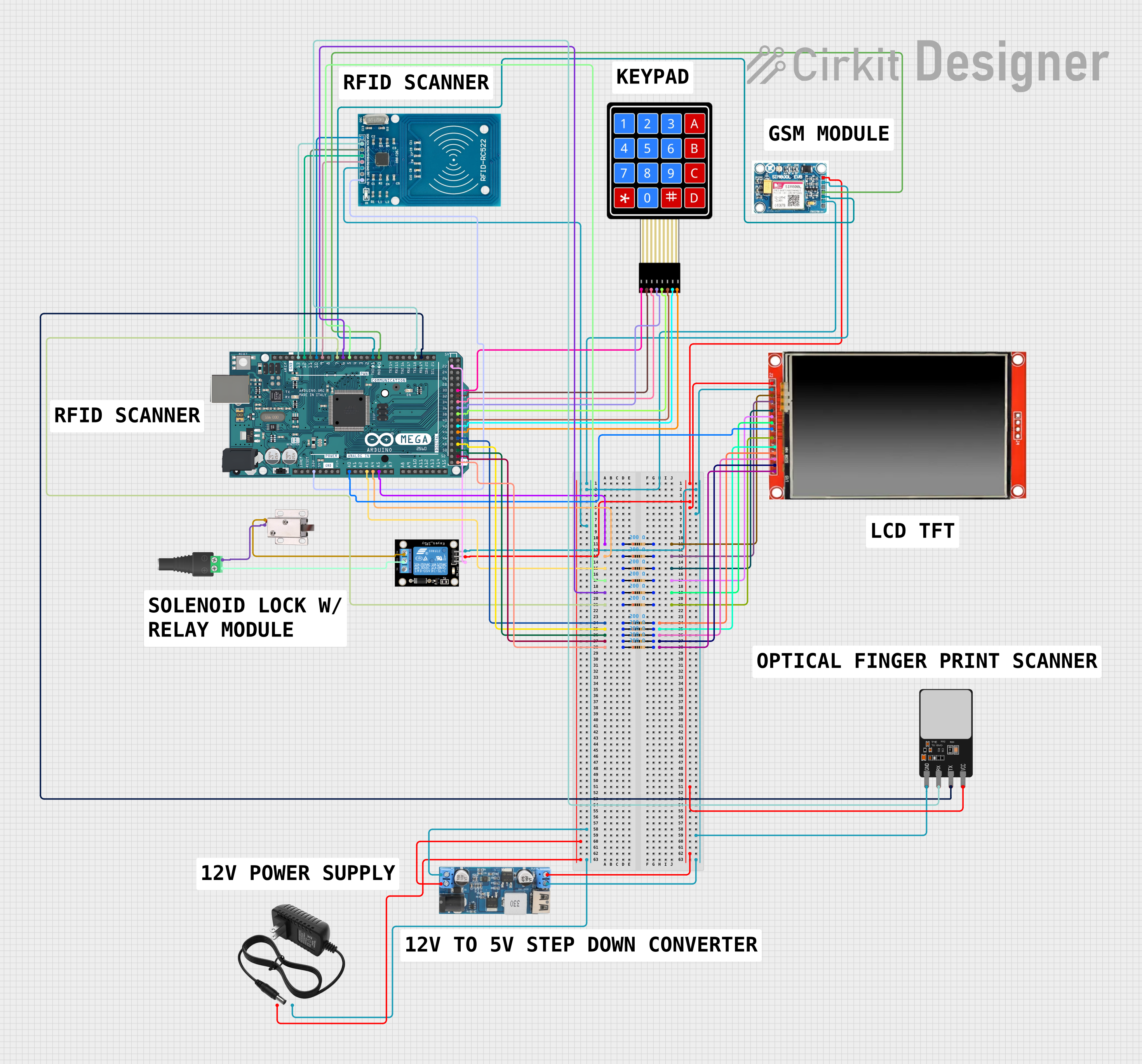
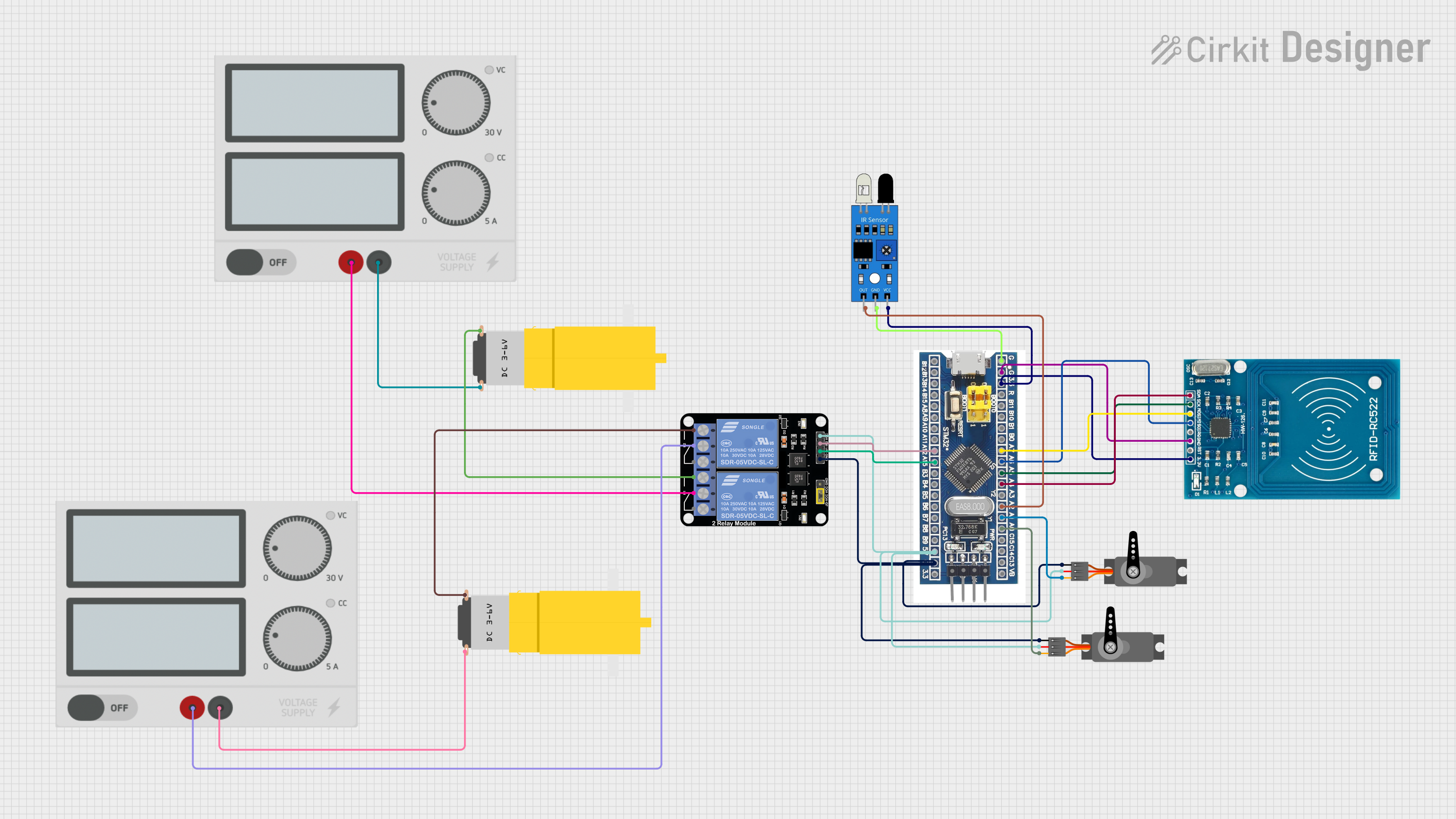


Explore Projects Built with RPLiDAR A2M8-R3
Common Applications:
- Autonomous robotic navigation and obstacle avoidance
- SLAM for mapping and localization
- Indoor and outdoor environment scanning
- Smart home automation and security systems
- Industrial automation and monitoring
Technical Specifications
Key Technical Details:
| Parameter | Specification |
|---|---|
| Scanning Range | 0.15 m to 12 m (indoor) |
| Scanning Angle | 360° |
| Angular Resolution | 0.45° - 1.35° (adjustable) |
| Sample Rate | Up to 8000 samples per second |
| Communication Interface | UART (3.3V TTL) |
| Input Voltage | 5V DC |
| Power Consumption | 4W (typical) |
| Operating Temperature | 0°C to 40°C |
| Dimensions | 70 mm (diameter) x 41 mm (height) |
| Weight | 190 g |
Pin Configuration and Descriptions:
The RPLiDAR A2M8-R3 uses a 5-pin connector for communication and power. Below is the pinout:
| Pin Number | Name | Description |
|---|---|---|
| 1 | VCC | 5V DC power input |
| 2 | GND | Ground |
| 3 | TX | UART Transmit (3.3V TTL) |
| 4 | RX | UART Receive (3.3V TTL) |
| 5 | MOTOCTL | Motor control signal (PWM input) |
Usage Instructions
How to Use the RPLiDAR A2M8-R3 in a Circuit:
- Power Supply: Connect the
VCCpin to a stable 5V DC power source and theGNDpin to ground. - Communication: Use the
TXandRXpins to establish UART communication with a microcontroller or computer. Ensure the UART voltage level is 3.3V TTL. - Motor Control: The
MOTOCTLpin can be used to control the motor speed via a PWM signal. Alternatively, the motor can run at a default speed if this pin is left unconnected. - Data Processing: Use the provided SDK or libraries to process the LiDAR data and integrate it into your application.
Important Considerations:
- Power Stability: Ensure a stable 5V power supply to avoid performance issues.
- UART Voltage Levels: Do not connect the UART pins directly to 5V logic devices; use a level shifter if necessary.
- Environment: While the sensor works in various environments, avoid direct exposure to sunlight or reflective surfaces, as these may affect accuracy.
- Mounting: Secure the LiDAR on a stable platform to minimize vibrations during operation.
Example: Connecting to an Arduino UNO
Below is an example of how to connect the RPLiDAR A2M8-R3 to an Arduino UNO and read data using the official SDK.
Wiring:
| RPLiDAR Pin | Arduino Pin |
|---|---|
| VCC | 5V |
| GND | GND |
| TX | RX (Pin 0) |
| RX | TX (Pin 1) |
| MOTOCTL | Not connected (default motor speed) |
Code Example:
#include <RPLidar.h> // Include the RPLiDAR library

RPLidar lidar; // Create an RPLidar object

void setup() {
  Serial.begin(115200); // Initialize serial communication
  lidar.begin(Serial);  // Start communication with the RPLiDAR

  // Wait for the RPLiDAR to initialize
  while (!lidar.checkHealth()) {
    Serial.println("RPLiDAR health check failed. Retrying...");
    delay(1000);
  }
  Serial.println("RPLiDAR is ready.");
}

void loop() {
  if (IS_OK(lidar.waitPoint())) {
    // Retrieve the distance and angle of the current scan point
    float distance = lidar.getCurrentPoint().distance; // Distance in mm
    float angle = lidar.getCurrentPoint().angle;       // Angle in degrees

    // Print the data to the Serial Monitor
    Serial.print("Distance: ");
    Serial.print(distance);
    Serial.print(" mm, Angle: ");
    Serial.print(angle);
    Serial.println(" degrees");
  } else {
    Serial.println("Failed to retrieve data from RPLiDAR.");
  }
}
Notes:
- Install the RPLiDAR Arduino library before running the code.
- Avoid using the Arduino's hardware serial port for debugging while connected to the RPLiDAR.
Troubleshooting and FAQs
Common Issues:
No Data Output:
- Cause: Incorrect wiring or baud rate mismatch.
- Solution: Verify the connections and ensure the baud rate matches the RPLiDAR's default (115200).
Motor Not Spinning:
- Cause: Insufficient power or
MOTOCTLpin not configured. - Solution: Check the power supply and ensure the
MOTOCTLpin is left unconnected or driven with a valid PWM signal.
- Cause: Insufficient power or
Inaccurate Measurements:
- Cause: Reflective or transparent surfaces in the environment.
- Solution: Avoid scanning highly reflective or transparent objects.
Health Check Fails:
- Cause: Sensor malfunction or communication error.
- Solution: Restart the sensor and check the UART connections.
FAQs:
Can the RPLiDAR A2M8-R3 be used outdoors? Yes, but avoid direct sunlight and extreme weather conditions for optimal performance.
What is the maximum range of the sensor? The maximum range is 12 meters indoors, but it may vary depending on environmental conditions.
Is the RPLiDAR compatible with Raspberry Pi? Yes, the RPLiDAR can be used with Raspberry Pi via UART or USB using the official SDK.
How do I clean the sensor? Use a soft, lint-free cloth to gently clean the LiDAR's lens. Avoid using liquids or abrasive materials.
This documentation provides a comprehensive guide to using the RPLiDAR A2M8-R3 effectively in your projects. For further details, refer to the official datasheet and SDK documentation.