Cirkit Designer Logo
Cirkit Designer
Your all-in-one circuit design IDE
Home / 
Component Documentation

How to Use LED CONTROLLER SW-301U-E3: Examples, Pinouts, and Specs

Image of LED CONTROLLER SW-301U-E3
Cirkit Designer LogoDesign with LED CONTROLLER SW-301U-E3 in Cirkit Designer

Introduction

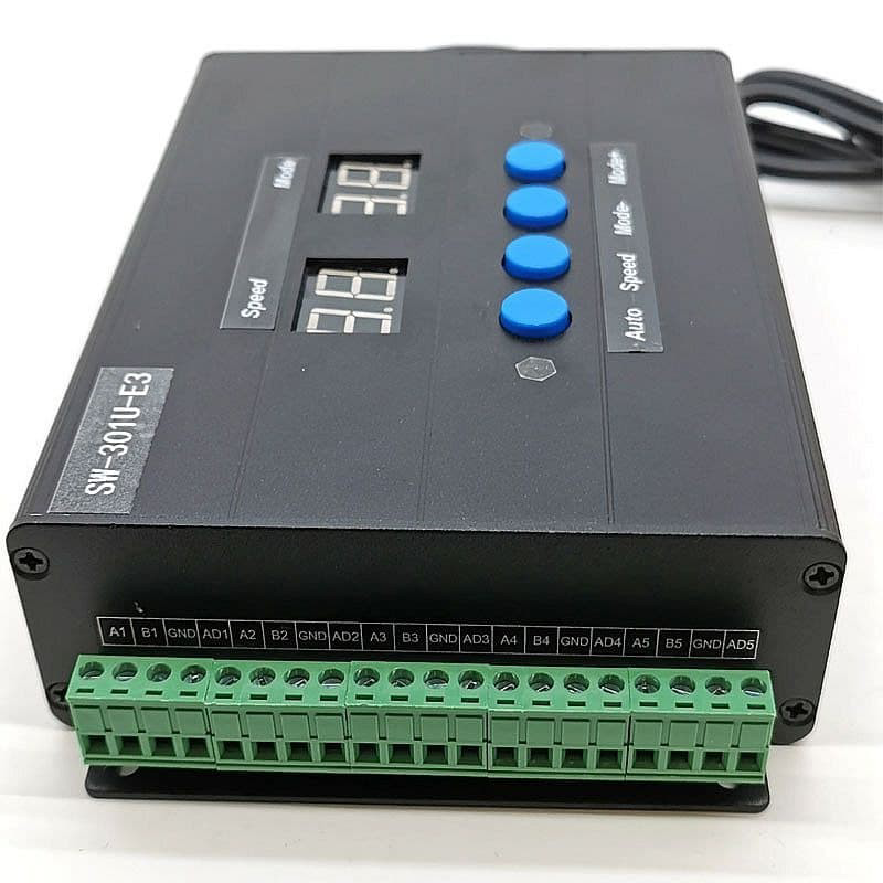
The SW-301U-E3 is a versatile LED controller designed to manage the brightness, color, and operation of LED lights. This component is widely used in various lighting systems, including residential, commercial, and industrial applications. It provides precise control over LED lighting, making it ideal for creating dynamic lighting effects, energy-efficient lighting solutions, and customized lighting environments.

Explore Projects Built with LED CONTROLLER SW-301U-E3

Use Cirkit Designer to design, explore, and prototype these projects online. Some projects support real-time simulation. Click "Open Project" to start designing instantly!
Wi-Fi Controlled Smart Light with ESP32 and Relay Module
Image of esp32 : A project utilizing LED CONTROLLER SW-301U-E3 in a practical application
This circuit is a smart home lighting control system using an ESP32 microcontroller to manage an AC bulb and an LED filament via a 5V relay module. The system allows for both manual control through physical switches and remote control via WiFi using the SinricPro platform.
Cirkit Designer LogoOpen Project in Cirkit Designer
Wi-Fi Enabled Motion-Activated Lighting System with Radar Sensor
Image of CAPSTONE: A project utilizing LED CONTROLLER SW-301U-E3 in a practical application
This circuit is designed to control an AC LED bulb using a 220V power source, with an infrared motion sensor and an MMWave radar sensor providing input signals. The two-channel relay is used to switch the LED bulb on and off based on the sensor inputs, while the ESP8266 microcontroller is likely programmed to process the sensor data and control the relay. A converter is included to interface between the sensors, microcontroller, and the relay, ensuring proper voltage levels.
Cirkit Designer LogoOpen Project in Cirkit Designer
ESP32C3 Supermini-Based Smart Environment Monitor and Lighting Control System
Image of Bedside RGB and Lamp: A project utilizing LED CONTROLLER SW-301U-E3 in a practical application
This is a smart control system featuring an ESP32C3 Supermini microcontroller for interfacing with various sensors and actuators. It includes temperature and humidity sensing, RGB LED strip control, user input via a pushbutton and rotary encoder, and AC power control through a two-channel relay. The system is powered by an AC source converted to DC by the HLK-PM12 module.
Cirkit Designer LogoOpen Project in Cirkit Designer
ESP8266 NodeMCU Controlled Smart Home Automation System
Image of home automation: A project utilizing LED CONTROLLER SW-301U-E3 in a practical application
This is a smart control system utilizing an ESP8266 NodeMCU to manage various devices through a 4-channel relay, with input from an LDR module and a PIR sensor. It is designed for both manual and automatic control, powered by a Li-ion battery and 240V AC source.
Cirkit Designer LogoOpen Project in Cirkit Designer

Explore Projects Built with LED CONTROLLER SW-301U-E3

Use Cirkit Designer to design, explore, and prototype these projects online. Some projects support real-time simulation. Click "Open Project" to start designing instantly!
Image of esp32 : A project utilizing LED CONTROLLER SW-301U-E3 in a practical application
Wi-Fi Controlled Smart Light with ESP32 and Relay Module
This circuit is a smart home lighting control system using an ESP32 microcontroller to manage an AC bulb and an LED filament via a 5V relay module. The system allows for both manual control through physical switches and remote control via WiFi using the SinricPro platform.
Cirkit Designer LogoOpen Project in Cirkit Designer
Image of CAPSTONE: A project utilizing LED CONTROLLER SW-301U-E3 in a practical application
Wi-Fi Enabled Motion-Activated Lighting System with Radar Sensor
This circuit is designed to control an AC LED bulb using a 220V power source, with an infrared motion sensor and an MMWave radar sensor providing input signals. The two-channel relay is used to switch the LED bulb on and off based on the sensor inputs, while the ESP8266 microcontroller is likely programmed to process the sensor data and control the relay. A converter is included to interface between the sensors, microcontroller, and the relay, ensuring proper voltage levels.
Cirkit Designer LogoOpen Project in Cirkit Designer
Image of Bedside RGB and Lamp: A project utilizing LED CONTROLLER SW-301U-E3 in a practical application
ESP32C3 Supermini-Based Smart Environment Monitor and Lighting Control System
This is a smart control system featuring an ESP32C3 Supermini microcontroller for interfacing with various sensors and actuators. It includes temperature and humidity sensing, RGB LED strip control, user input via a pushbutton and rotary encoder, and AC power control through a two-channel relay. The system is powered by an AC source converted to DC by the HLK-PM12 module.
Cirkit Designer LogoOpen Project in Cirkit Designer
Image of home automation: A project utilizing LED CONTROLLER SW-301U-E3 in a practical application
ESP8266 NodeMCU Controlled Smart Home Automation System
This is a smart control system utilizing an ESP8266 NodeMCU to manage various devices through a 4-channel relay, with input from an LDR module and a PIR sensor. It is designed for both manual and automatic control, powered by a Li-ion battery and 240V AC source.
Cirkit Designer LogoOpen Project in Cirkit Designer

Technical Specifications

Key Technical Details

Parameter Value
Manufacturer SW-301U-E3
Part ID SW-301U-E3
Input Voltage 5V - 24V DC
Output Current Up to 5A per channel
Number of Channels 3 (RGB)
Control Interface PWM, DMX512, RF, IR
Operating Temperature -20°C to 60°C
Dimensions 85mm x 45mm x 23mm

Pin Configuration and Descriptions

Pin Number Pin Name Description
1 VCC Power supply input (5V - 24V DC)
2 GND Ground
3 CH1 Channel 1 output (Red)
4 CH2 Channel 2 output (Green)
5 CH3 Channel 3 output (Blue)
6 PWM PWM control signal input
7 DMX+ DMX512 control signal positive
8 DMX- DMX512 control signal negative
9 RF RF control signal input
10 IR IR control signal input

Usage Instructions

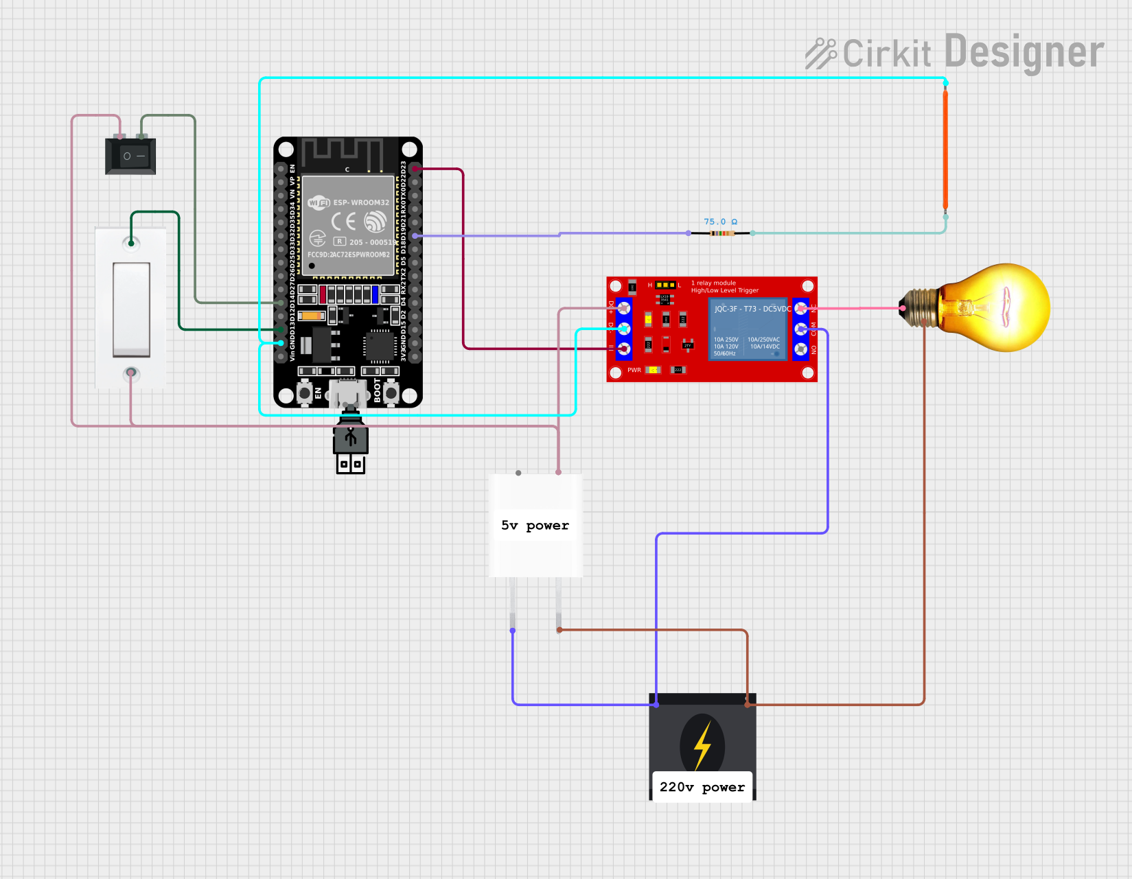
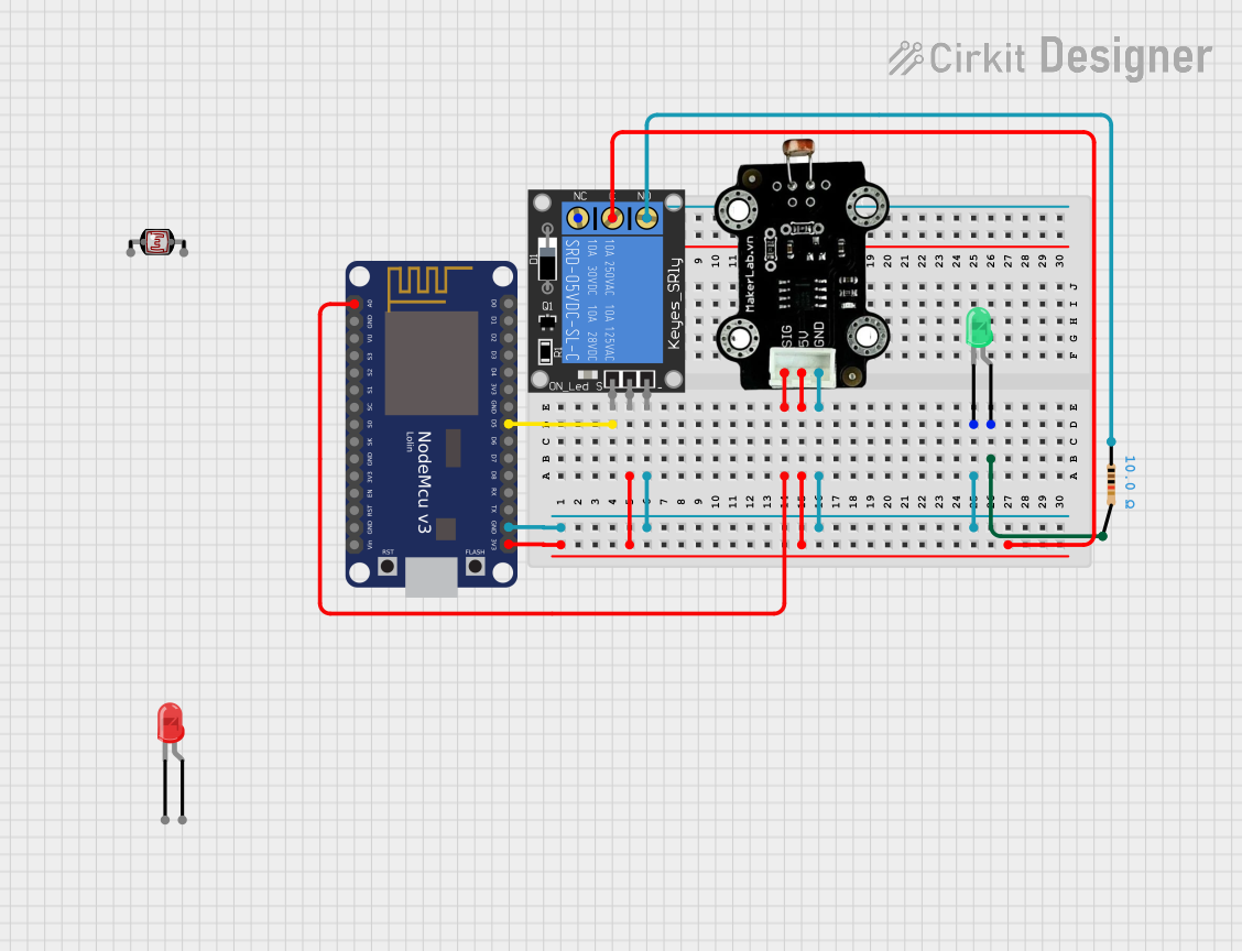
How to Use the Component in a Circuit

  1. Power Supply Connection:

    • Connect the VCC pin to a DC power supply (5V - 24V).
    • Connect the GND pin to the ground of the power supply.
  2. LED Connection:

    • Connect the anode of the Red LED to CH1.
    • Connect the anode of the Green LED to CH2.
    • Connect the anode of the Blue LED to CH3.
    • Connect the cathodes of all LEDs to the ground.
  3. Control Signal Connection:

    • For PWM control, connect the PWM pin to the PWM output of a microcontroller (e.g., Arduino).
    • For DMX512 control, connect the DMX+ and DMX- pins to the DMX512 controller.
    • For RF control, connect the RF pin to the RF controller.
    • For IR control, connect the IR pin to the IR controller.

Important Considerations and Best Practices

  • Ensure that the power supply voltage matches the voltage rating of the LEDs.
  • Use appropriate current-limiting resistors to prevent overcurrent through the LEDs.
  • Keep the controller in a well-ventilated area to avoid overheating.
  • Follow the manufacturer's guidelines for maximum current ratings to ensure safe operation.

Example Code for Arduino UNO

Below is an example code to control the SW-301U-E3 using an Arduino UNO with PWM signals.

// Define PWM pins for Red, Green, and Blue channels
const int redPin = 9;
const int greenPin = 10;
const int bluePin = 11;

void setup() {
  // Set the PWM pins as output
  pinMode(redPin, OUTPUT);
  pinMode(greenPin, OUTPUT);
  pinMode(bluePin, OUTPUT);
}

void loop() {
  // Example: Fade Red LED in and out
  for (int brightness = 0; brightness <= 255; brightness++) {
    analogWrite(redPin, brightness); // Increase brightness
    delay(10); // Wait for 10 milliseconds
  }
  for (int brightness = 255; brightness >= 0; brightness--) {
    analogWrite(redPin, brightness); // Decrease brightness
    delay(10); // Wait for 10 milliseconds
  }
}

Troubleshooting and FAQs

Common Issues Users Might Face

  1. LEDs Not Lighting Up:

    • Check the power supply connection and ensure it matches the required voltage.
    • Verify that the LEDs are connected correctly and the anodes are connected to the correct channels.
  2. Flickering LEDs:

    • Ensure that the PWM frequency is appropriate for the LEDs.
    • Check for loose connections or poor solder joints.
  3. Overheating:

    • Ensure proper ventilation around the controller.
    • Verify that the current through each channel does not exceed the maximum rating.

Solutions and Tips for Troubleshooting

  • Power Supply Issues: Use a multimeter to check the voltage at the VCC and GND pins.
  • Connection Issues: Double-check all connections and ensure they are secure.
  • Control Signal Issues: Verify that the control signals (PWM, DMX512, RF, IR) are correctly connected and configured.

By following this documentation, users can effectively utilize the SW-301U-E3 LED controller in their lighting projects, ensuring optimal performance and reliability.