How to Use Logic Level Shifter Converter Module: Examples, Pinouts, and Specs
Introduction
The Logic Level Shifter Converter Module is a device designed to facilitate communication between circuits operating at different voltage levels. It enables the safe and effective conversion of signals from one logic level to another, ensuring compatibility between components that use different voltage standards. This module is particularly useful in mixed-voltage systems, such as interfacing 3.3V microcontrollers with 5V sensors or peripherals.
Explore Projects Built with Logic Level Shifter Converter Module


Explore Projects Built with Logic Level Shifter Converter Module
Common Applications and Use Cases
- Interfacing 3.3V microcontrollers (e.g., ESP32, Raspberry Pi) with 5V devices (e.g., Arduino, sensors).
- Communication between I2C, SPI, or UART devices operating at different voltage levels.
- Mixed-voltage systems in robotics, IoT, and embedded systems.
- Protecting low-voltage devices from damage caused by higher voltage signals.
Technical Specifications
Key Technical Details
- Voltage Levels Supported: 1.8V, 3.3V, 5V (common configurations).
- Channels: Typically 4 bidirectional channels.
- Current Consumption: Minimal, typically in the range of a few milliamps.
- Communication Protocols Supported: I2C, SPI, UART, GPIO.
- Operating Temperature: -40°C to 85°C (varies by manufacturer).
- Dimensions: Compact, typically 15mm x 15mm.
Pin Configuration and Descriptions
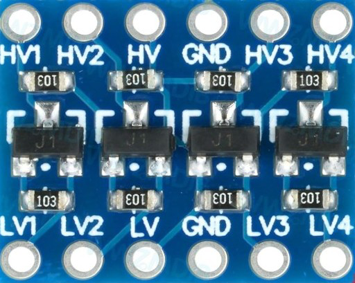
The module typically has 8 pins, divided into two voltage domains: high voltage (HV) and low voltage (LV).
| Pin Name | Description |
|---|---|
| HV | High voltage input (e.g., 5V). Connect to the higher voltage power source. |
| LV | Low voltage input (e.g., 3.3V). Connect to the lower voltage power source. |
| GND | Ground. Common ground for both voltage domains. |
| HV1, HV2, HV3, HV4 | High voltage signal pins. Connect to the high voltage side of the circuit. |
| LV1, LV2, LV3, LV4 | Low voltage signal pins. Connect to the low voltage side of the circuit. |
Usage Instructions
How to Use the Component in a Circuit
Power the Module:
- Connect the HV pin to the higher voltage power source (e.g., 5V).
- Connect the LV pin to the lower voltage power source (e.g., 3.3V).
- Connect the GND pin to the common ground of the system.
Connect Signal Lines:
- For each signal line, connect the high voltage side (e.g., HV1) to the device operating at the higher voltage.
- Connect the corresponding low voltage side (e.g., LV1) to the device operating at the lower voltage.
Verify Connections:
- Ensure that the voltage levels on the HV and LV sides match the requirements of the connected devices.
- Double-check the ground connection to avoid communication issues.
Important Considerations and Best Practices
- Voltage Compatibility: Ensure that the voltage levels on the HV and LV sides are within the module's supported range.
- Signal Integrity: Keep signal lines as short as possible to minimize noise and ensure reliable communication.
- Power Supply: Use stable and regulated power supplies for both HV and LV inputs.
- I2C Pull-Up Resistors: If using the module for I2C communication, ensure that appropriate pull-up resistors are present on the SDA and SCL lines.
Example: Connecting to an Arduino UNO
Below is an example of using the Logic Level Shifter Converter Module to interface a 3.3V sensor with a 5V Arduino UNO.
Circuit Diagram
- HV: Connect to the Arduino's 5V pin.
- LV: Connect to the sensor's 3.3V power pin.
- GND: Connect to the common ground of the Arduino and sensor.
- HV1: Connect to the Arduino's digital pin (e.g., D2).
- LV1: Connect to the sensor's data pin.
Arduino Code Example
// Example: Reading data from a 3.3V sensor using a 5V Arduino UNO
// Ensure the Logic Level Shifter is properly connected as described above.

const int sensorPin = 2; // Arduino pin connected to HV1 on the level shifter

void setup() {
  Serial.begin(9600); // Initialize serial communication
  pinMode(sensorPin, INPUT); // Set the sensor pin as input
}

void loop() {
  int sensorValue = digitalRead(sensorPin); // Read the sensor value
  Serial.println(sensorValue); // Print the sensor value to the Serial Monitor
  delay(500); // Wait for 500ms before the next reading
}
Troubleshooting and FAQs
Common Issues and Solutions
No Communication Between Devices:
- Cause: Incorrect voltage levels or missing connections.
- Solution: Verify that the HV and LV pins are connected to the correct voltage sources. Check all signal connections.
Signal Distortion or Noise:
- Cause: Long signal lines or poor grounding.
- Solution: Shorten signal lines and ensure a solid ground connection.
I2C Communication Fails:
- Cause: Missing or incorrect pull-up resistors.
- Solution: Add appropriate pull-up resistors (e.g., 4.7kΩ) to the SDA and SCL lines.
Overheating Module:
- Cause: Exceeding the module's voltage or current limits.
- Solution: Ensure that the voltage and current levels are within the module's specifications.
FAQs
Q: Can this module be used for analog signals?
A: No, the module is designed for digital signals only. For analog signals, use a dedicated level shifter or voltage divider.Q: How many channels can I use simultaneously?
A: Most modules support 4 bidirectional channels, but check the specific module's datasheet for details.Q: Can I use this module with a 1.8V device?
A: Yes, as long as the module supports 1.8V on the LV side. Verify the specifications before use.Q: Do I need external power for the module?
A: No, the module is powered by the HV and LV inputs provided by the connected devices.