How to Use HEF4094: Examples, Pinouts, and Specs

Introduction
The HEF4094 is an integrated circuit that functions as an 8-bit serial-in, serial or parallel-out shift register. This component is particularly useful in applications where there is a need to expand the number of output pins available on a microcontroller, such as the Arduino UNO. It allows for the control of multiple devices using a minimal number of I/O pins by shifting data serially into the register and then outputting it in either a serial or parallel format. Common applications include driving LEDs, LCDs, and other digital devices in a variety of electronic projects.
Explore Projects Built with HEF4094
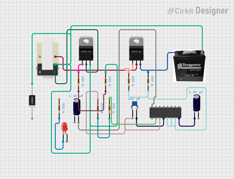
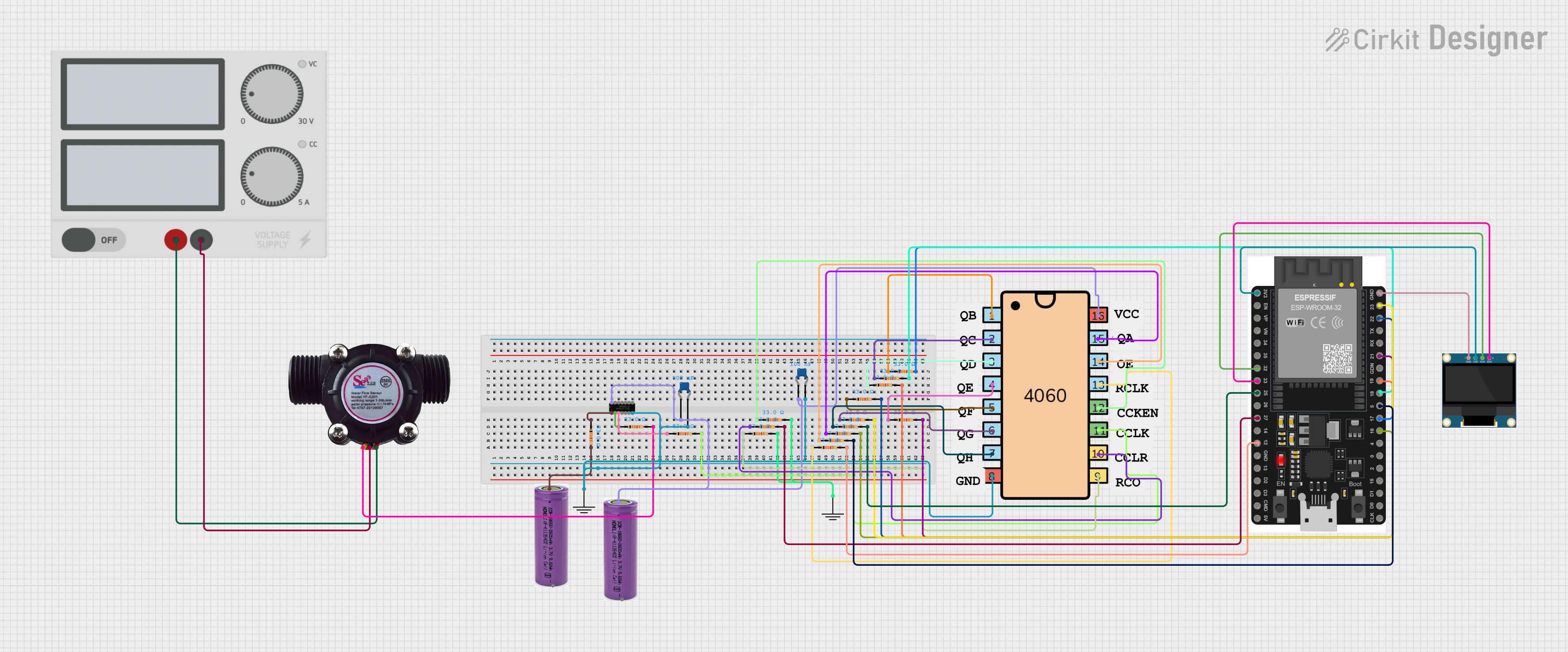


Explore Projects Built with HEF4094
Technical Specifications
Key Technical Details
- Supply Voltage (Vcc): 3 V to 15 V
- Clock Frequency (Max): 25 MHz at Vcc = 15 V
- Output Current (Max per Pin): 25 mA
- Operating Temperature Range: -40°C to +85°C
- Package Type: Available in SO16 and DIP16 packages
Pin Configuration and Descriptions
| Pin Number | Name | Description |
|---|---|---|
| 1 | Q7' | Serial output for cascading |
| 2 | Q0 | Parallel output 0 |
| 3 | Q1 | Parallel output 1 |
| 4 | Q2 | Parallel output 2 |
| 5 | Q3 | Parallel output 3 |
| 6 | Q4 | Parallel output 4 |
| 7 | Q5 | Parallel output 5 |
| 8 | GND | Ground (0V) |
| 9 | Q6 | Parallel output 6 |
| 10 | Q7 | Parallel output 7 |
| 11 | /OE | Output enable (active LOW) |
| 12 | ST_CP | Strobe input |
| 13 | DATA | Serial data input |
| 14 | CLK | Clock input |
| 15 | STR | Storage register clock input |
| 16 | Vcc | Positive supply voltage |
Usage Instructions
How to Use the HEF4094 in a Circuit
- Power Supply: Connect pin 16 (Vcc) to the positive supply voltage (3 V to 15 V) and pin 8 (GND) to the ground.
- Data Input: Apply the serial data to pin 13 (DATA) that you want to shift into the register.
- Clocking Data: Apply a clock signal to pin 14 (CLK) to shift the data into the register.
- Output Enable: To enable the outputs, connect pin 11 (/OE) to ground. If you wish to disable the outputs, apply a high signal to this pin.
- Strobe Input: Use pin 12 (ST_CP) to transfer data from the shift register to the storage register. This allows for parallel output on pins Q0 to Q7.
- Cascading Units: If more than 8 bits are required, the serial output on pin 1 (Q7') can be connected to the serial data input of the next HEF4094.
Important Considerations and Best Practices
- Ensure that the supply voltage does not exceed the maximum rating of 15 V to prevent damage to the IC.
- It is recommended to use a decoupling capacitor (e.g., 0.1 µF) between Vcc and GND near the IC to filter out noise.
- Avoid floating inputs by connecting unused pins to a defined logic level.
- When cascading multiple HEF4094 ICs, ensure that the clock and strobe signals are distributed uniformly to all ICs.
Example Code for Arduino UNO
// Define the pins connected to the HEF4094
const int dataPin = 2;    // HEF4094 Pin 13 - DATA
const int clockPin = 3;   // HEF4094 Pin 14 - CLK
const int strobePin = 4;  // HEF4094 Pin 12 - ST_CP

void setup() {
  // Set pins as outputs
  pinMode(dataPin, OUTPUT);
  pinMode(clockPin, OUTPUT);
  pinMode(strobePin, OUTPUT);
}

void loop() {
  // Example: shift out the number 255 (binary 11111111)
  shiftOut(dataPin, clockPin, MSBFIRST, 255);
  // Strobe the register to output the data
  digitalWrite(strobePin, HIGH);
  delay(1); // Wait for a moment
  digitalWrite(strobePin, LOW);
  delay(1000); // Wait for a second
}

// Note: The above code assumes that /OE is connected to GND
Troubleshooting and FAQs
Common Issues
- No Output on Pins Q0-Q7: Ensure that /OE is connected to ground and that the ST_CP pin has been pulsed high after data is clocked in.
- Inconsistent Output: Check for loose connections and ensure that the clock signal is clean and free of noise.
- Unexpected Behavior When Cascading: Verify that the Q7' of one IC is correctly connected to the DATA input of the next IC and that all ICs receive the same clock and strobe signals.
Solutions and Tips for Troubleshooting
- Use an oscilloscope to check the clock and data signals for integrity.
- Ensure that the power supply is stable and within the specified voltage range.
- If using long wires or cables, consider the effects of capacitance and electromagnetic interference on signal quality.
FAQs
Q: Can the HEF4094 be used with a 5V Arduino? A: Yes, the HEF4094 can operate at 5V, making it compatible with 5V microcontrollers like the Arduino UNO.
Q: How do I reset the HEF4094? A: The HEF4094 does not have a dedicated reset pin. To reset, you can clear the register by shifting in zeros and strobing the output.
Q: Can I use the HEF4094 to drive power-hungry devices? A: The HEF4094 can source or sink up to 25 mA per pin. For devices requiring more current, use a transistor or a driver IC to amplify the current.