How to Use DC Converter (Adapter): Examples, Pinouts, and Specs
Introduction
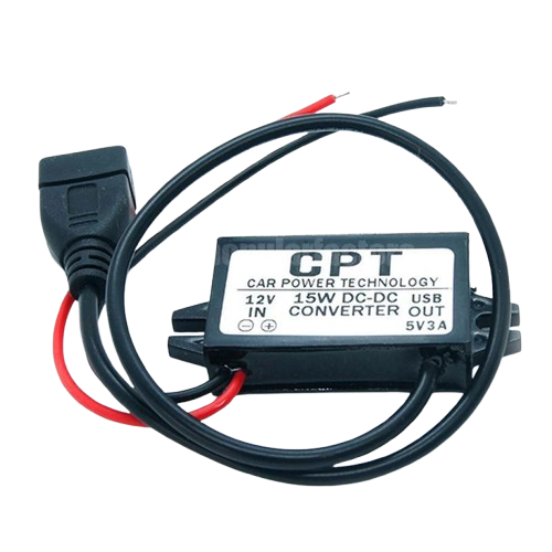
A DC Converter, also known as a DC adapter, is an electronic device designed to convert direct current (DC) from one voltage level to another. It is commonly used to power electronic devices that require a specific voltage level, different from the source voltage. DC converters are essential in applications where devices need to operate efficiently and safely without being damaged by incorrect voltage levels.
Explore Projects Built with DC Converter (Adapter)


Explore Projects Built with DC Converter (Adapter)
Common Applications and Use Cases
- Powering microcontrollers, sensors, and modules in embedded systems.
- Charging batteries with a specific voltage requirement.
- Supplying power to portable devices from a higher or lower voltage source.
- Voltage regulation in automotive, industrial, and renewable energy systems.
- Step-up (boost) or step-down (buck) voltage conversion for LED drivers and motor controllers.
Technical Specifications
Below are the general technical specifications for a typical DC converter. Note that actual values may vary depending on the specific model or type of converter (e.g., buck, boost, or buck-boost).
General Specifications
| Parameter | Value/Range |
|---|---|
| Input Voltage Range | 5V to 36V (varies by model) |
| Output Voltage Range | 1.2V to 24V (adjustable or fixed) |
| Output Current | Up to 5A (varies by model) |
| Efficiency | Up to 95% (depending on load) |
| Switching Frequency | 150 kHz to 1 MHz |
| Operating Temperature | -40°C to +85°C |
| Protection Features | Overcurrent, overvoltage, thermal |
Pin Configuration and Descriptions
The pin configuration of a DC converter depends on its design. Below is a typical pinout for a module-based DC converter:
| Pin Name | Description |
|---|---|
| VIN | Input voltage pin (connect to the power source) |
| GND | Ground pin (common ground for input and output) |
| VOUT | Output voltage pin (connect to the load) |
| ADJ (optional) | Voltage adjustment pin (for adjustable models) |
Usage Instructions
How to Use the Component in a Circuit
Determine Input and Output Requirements:
- Identify the input voltage range of your power source.
- Determine the required output voltage and current for your load.
Connect the Input:
- Connect the positive terminal of your power source to the
VINpin. - Connect the negative terminal of your power source to the
GNDpin.
- Connect the positive terminal of your power source to the
Set the Output Voltage (if adjustable):
- For adjustable models, use the
ADJpin or onboard potentiometer to set the desired output voltage. - Measure the output voltage using a multimeter to ensure accuracy.
- For adjustable models, use the
Connect the Load:
- Connect the positive terminal of your load to the
VOUTpin. - Connect the negative terminal of your load to the
GNDpin.
- Connect the positive terminal of your load to the
Power On:
- Turn on the power source and verify the output voltage and current.
Important Considerations and Best Practices
- Input Voltage Range: Ensure the input voltage is within the specified range to avoid damaging the converter.
- Heat Dissipation: For high-power applications, use a heatsink or active cooling to prevent overheating.
- Load Compatibility: Verify that the load does not exceed the maximum output current of the converter.
- Polarity: Double-check the polarity of connections to avoid short circuits or damage.
- Filtering: Add input and output capacitors if the circuit requires additional noise filtering.
Example: Using a DC Converter with an Arduino UNO
Below is an example of using a DC converter to power an Arduino UNO from a 12V source:
- Set the DC converter output to 5V using the onboard potentiometer.
- Connect the 12V source to the
VINandGNDpins of the converter. - Connect the
VOUTpin of the converter to the5Vpin of the Arduino UNO. - Connect the
GNDpin of the converter to theGNDpin of the Arduino UNO.
// Example Arduino code to blink an LED powered by a DC converter

const int ledPin = 13; // Pin connected to the onboard LED

void setup() {
  pinMode(ledPin, OUTPUT); // Set the LED pin as an output
}

void loop() {
  digitalWrite(ledPin, HIGH); // Turn the LED on
  delay(1000);                // Wait for 1 second
  digitalWrite(ledPin, LOW);  // Turn the LED off
  delay(1000);                // Wait for 1 second
}
Troubleshooting and FAQs
Common Issues and Solutions
| Issue | Possible Cause | Solution |
|---|---|---|
| No output voltage | Incorrect input connections | Verify input polarity and connections. |
| Output voltage is unstable | Insufficient input filtering | Add input capacitors (e.g., 100µF). |
| Overheating | Excessive load or poor ventilation | Reduce load or add a heatsink. |
| Output voltage not adjustable | Faulty potentiometer or adjustment pin | Check and replace the potentiometer. |
| Load not powering on | Output current too low | Use a converter with a higher current rating. |
FAQs
Can I use a DC converter to charge a battery?
- Yes, but ensure the output voltage and current are suitable for the battery type.
What happens if I exceed the input voltage range?
- Exceeding the input voltage range can damage the converter. Always stay within the specified range.
Can I use a DC converter with an AC power source?
- No, DC converters are designed for DC input only. Use an AC-DC adapter to convert AC to DC first.
How do I know if my DC converter is efficient?
- Check the efficiency rating in the datasheet. Higher efficiency means less energy is lost as heat.
By following this documentation, you can effectively use a DC converter in your projects while ensuring safety and reliability.