How to Use Digilent PMod Gyro: Examples, Pinouts, and Specs
Introduction
The Digilent PMod Gyro is a digital gyroscope module designed to measure angular velocity with high precision. It is based on the STMicroelectronics L3G4200D gyroscope sensor, which provides three-axis motion sensing capabilities. This module is ideal for applications requiring accurate motion tracking, such as robotics, drones, gaming devices, and other motion-sensing systems. Its compact design and SPI/I2C communication interfaces make it easy to integrate into a wide range of projects.
Explore Projects Built with Digilent PMod Gyro
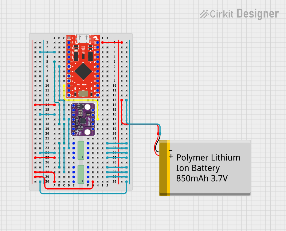
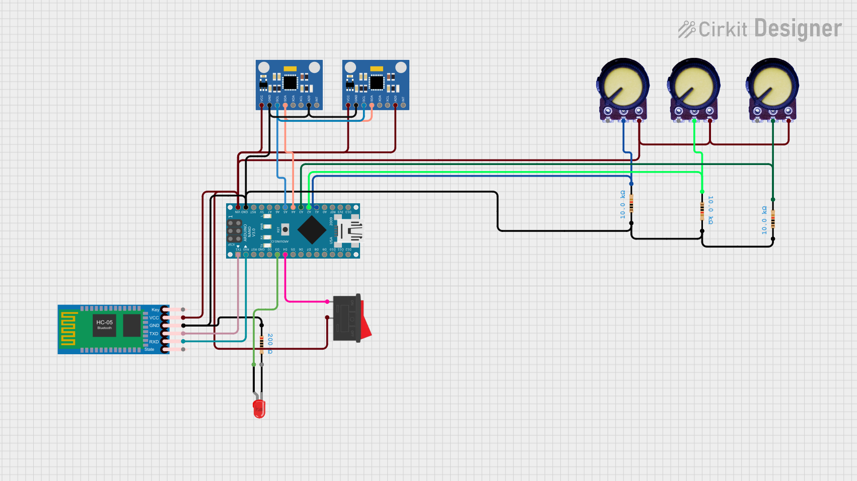
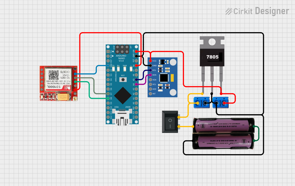

Explore Projects Built with Digilent PMod Gyro
Common Applications
- Robotics for motion tracking and stabilization
- Drones for flight control and orientation sensing
- Gaming devices for motion-based input
- Wearable devices for activity monitoring
- Industrial equipment for vibration and motion analysis
Technical Specifications
The following are the key technical details of the Digilent PMod Gyro:
| Parameter | Value |
|---|---|
| Sensor | L3G4200D (STMicroelectronics) |
| Measurement Range | ±250, ±500, ±2000 degrees per second (dps) |
| Communication Interface | SPI or I2C |
| Supply Voltage | 3.3V |
| Operating Current | 6.1 mA (typical) |
| Output Data Rate (ODR) | Up to 800 Hz |
| Dimensions | 0.8" × 0.8" (20.32 mm × 20.32 mm) |
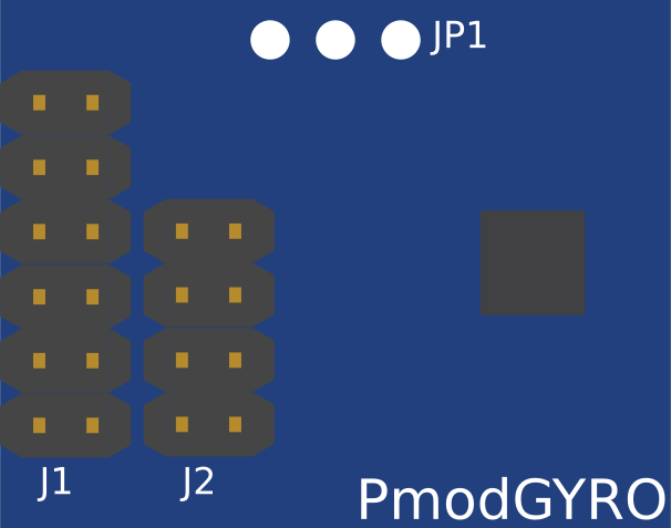
Pin Configuration and Descriptions
The PMod Gyro uses a 6-pin interface for communication and power. The pinout is as follows:
| Pin | Name | Description |
|---|---|---|
| 1 | CS | Chip Select (Active Low) for SPI communication |
| 2 | SDI/SDA | Serial Data Input (SPI) / Data Line (I2C) |
| 3 | SDO | Serial Data Output (SPI) |
| 4 | SCL | Serial Clock Line (SPI/I2C) |
| 5 | GND | Ground |
| 6 | VCC | Power Supply (3.3V) |
Usage Instructions
How to Use the PMod Gyro in a Circuit
- Power the Module: Connect the VCC pin to a 3.3V power source and the GND pin to ground.
- Choose Communication Protocol: Decide whether to use SPI or I2C for communication. For SPI, connect the CS, SDI, SDO, and SCL pins to the corresponding pins on your microcontroller. For I2C, connect the SDA and SCL pins to the I2C bus.
- Configure the Sensor: Use the appropriate library or write custom code to initialize the L3G4200D sensor. Set the desired measurement range, output data rate, and other parameters.
- Read Data: Continuously read angular velocity data from the sensor registers. The data will be provided in three axes: X, Y, and Z.
Important Considerations and Best Practices
- Voltage Compatibility: The PMod Gyro operates at 3.3V. Ensure that your microcontroller's I/O pins are 3.3V tolerant or use a level shifter if necessary.
- Mounting Orientation: Properly align the module in your system to ensure accurate motion sensing. The axes are marked on the module for reference.
- Noise Filtering: Use the built-in low-pass filter of the L3G4200D to reduce noise in the angular velocity readings.
- SPI/I2C Pull-Up Resistors: If using I2C, ensure that appropriate pull-up resistors are present on the SDA and SCL lines.
Example Code for Arduino UNO (SPI Communication)
#include <SPI.h>

// Define pin connections
const int CS_PIN = 10; // Chip Select pin connected to Arduino pin 10

void setup() {
  // Initialize Serial Monitor for debugging
  Serial.begin(9600);

  // Configure Chip Select pin as output
  pinMode(CS_PIN, OUTPUT);
  digitalWrite(CS_PIN, HIGH); // Set CS pin high (inactive)

  // Initialize SPI communication
  SPI.begin();
  SPI.setClockDivider(SPI_CLOCK_DIV16); // Set SPI clock speed
  SPI.setDataMode(SPI_MODE3);           // Set SPI mode
  SPI.setBitOrder(MSBFIRST);            // Set bit order

  // Initialize the gyroscope
  initializeGyro();
}

void loop() {
  // Read angular velocity data
  int16_t x = readGyroAxis(0x28); // X-axis register
  int16_t y = readGyroAxis(0x2A); // Y-axis register
  int16_t z = readGyroAxis(0x2C); // Z-axis register

  // Print data to Serial Monitor
  Serial.print("X: ");
  Serial.print(x);
  Serial.print(" Y: ");
  Serial.print(y);
  Serial.print(" Z: ");
  Serial.println(z);

  delay(100); // Delay for readability
}

void initializeGyro() {
  // Write to CTRL_REG1 to enable the gyroscope
  writeRegister(0x20, 0x0F); // Power on, enable all axes, 100 Hz ODR
}

void writeRegister(byte reg, byte value) {
  digitalWrite(CS_PIN, LOW); // Select the gyroscope
  SPI.transfer(reg);         // Send register address
  SPI.transfer(value);       // Send value to write
  digitalWrite(CS_PIN, HIGH); // Deselect the gyroscope
}

int16_t readGyroAxis(byte reg) {
  digitalWrite(CS_PIN, LOW); // Select the gyroscope
  SPI.transfer(reg | 0x80);  // Send register address with read bit
  byte lowByte = SPI.transfer(0x00); // Read low byte
  byte highByte = SPI.transfer(0x00); // Read high byte
  digitalWrite(CS_PIN, HIGH); // Deselect the gyroscope

  // Combine high and low bytes into a 16-bit value
  return (int16_t)((highByte << 8) | lowByte);
}
Troubleshooting and FAQs
Common Issues
No Data Output:
- Ensure the module is powered correctly (3.3V on VCC and GND connected).
- Verify that the communication protocol (SPI/I2C) is configured properly in your code.
- Check the connections between the PMod Gyro and the microcontroller.
Incorrect or Noisy Readings:
- Ensure the module is mounted securely to avoid vibrations.
- Use the low-pass filter settings in the L3G4200D to reduce noise.
- Verify that the measurement range is appropriate for your application.
Communication Errors:
- For SPI, ensure the CS pin is toggled correctly in your code.
- For I2C, check that pull-up resistors are present on the SDA and SCL lines.
FAQs
Q: Can I use the PMod Gyro with a 5V microcontroller?
A: The PMod Gyro operates at 3.3V. If your microcontroller operates at 5V, you will need a level shifter to safely interface with the module.
Q: How do I change the measurement range?
A: The measurement range can be configured by writing to the CTRL_REG4 register of the L3G4200D. Refer to the sensor's datasheet for details.
Q: What is the maximum sampling rate of the PMod Gyro?
A: The maximum output data rate (ODR) is 800 Hz, which can be configured in the CTRL_REG1 register.
Q: Can I use both SPI and I2C simultaneously?
A: No, the PMod Gyro supports either SPI or I2C communication, but not both at the same time. Select one protocol based on your application requirements.