Cirkit Designer Logo
Cirkit Designer
Your all-in-one circuit design IDE
Home / 
Component Documentation

How to Use Serial Expansion Board: Examples, Pinouts, and Specs

Image of Serial Expansion Board
Cirkit Designer LogoDesign with Serial Expansion Board in Cirkit Designer

Introduction

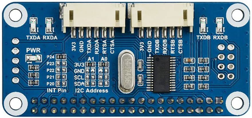
The Serial Expansion Board by Waveshare is an essential hardware component designed to increase the number of serial ports available on a computer or microcontroller system. This board is particularly useful in applications where multiple serial devices need to be connected, such as in industrial automation, robotics, data logging, and sensor networks.

Explore Projects Built with Serial Expansion Board

Use Cirkit Designer to design, explore, and prototype these projects online. Some projects support real-time simulation. Click "Open Project" to start designing instantly!
ESP32-Based Industrial Control System with RS485 Communication and I2C Interface
Image of DRIVER TESTER : A project utilizing Serial Expansion Board in a practical application
This circuit integrates a microcontroller with a display, digital potentiometer, IO expander, and opto-isolator board for signal interfacing and isolation. It includes a UART to RS485 converter for serial communication and a power converter to step down voltage for the system. The circuit is designed for control and communication in an isolated and protected environment.
Cirkit Designer LogoOpen Project in Cirkit Designer
ESP32-Based Vibration Motor Controller with I2C IO Expansion
Image of VIBRATYION: A project utilizing Serial Expansion Board in a practical application
This circuit features an ESP32 Wroom Dev Kit microcontroller interfaced with an MCP23017 I/O expansion board via I2C communication, utilizing GPIO 21 and GPIO 22 for SDA and SCL lines, respectively. A vibration motor is controlled by an NPN transistor acting as a switch, with a diode for back EMF protection and a resistor to limit base current. The ESP32 can control the motor by sending signals to the MCP23017, which then interfaces with the transistor to turn the motor on or off.
Cirkit Designer LogoOpen Project in Cirkit Designer
Arduino-Controlled Robotic Vehicle with Soil Moisture Sensing and Infrared Proximity Detection
Image of Irrigator Robot: A project utilizing Serial Expansion Board in a practical application
This circuit is designed to control multiple motors and sensors using an Arduino Expansion Board. It includes two TB6612FNG Motor Drivers to manage four DC motors and a 28BYJ-48 Stepper Motor, providing precise movement control. Additionally, the circuit integrates three Infrared Proximity Sensors and a DFRobot Capacitive Soil Moisture Sensor, interfaced with the Arduino's analog and digital pins for environmental sensing.
Cirkit Designer LogoOpen Project in Cirkit Designer
I2C-Controlled Relay Switching with ESP32 and MCP23017 for Home Automation
Image of Vloerverwarming: A project utilizing Serial Expansion Board in a practical application
This circuit appears to be a control system utilizing two MCP23017 I/O expanders interfaced with an Olimex ESP32-EVB microcontroller via I2C communication, as indicated by the SDA and SCL connections with pull-up resistors. The MCP23017 expanders control an 8-channel relay module, allowing the microcontroller to switch various loads, potentially for home automation or industrial control. Additionally, there is an Adafruit ADS1115 16-bit ADC for analog signal measurement, and several heating actuators and a thermostat are connected, suggesting temperature control functionality.
Cirkit Designer LogoOpen Project in Cirkit Designer

Explore Projects Built with Serial Expansion Board

Use Cirkit Designer to design, explore, and prototype these projects online. Some projects support real-time simulation. Click "Open Project" to start designing instantly!
Image of DRIVER TESTER : A project utilizing Serial Expansion Board in a practical application
ESP32-Based Industrial Control System with RS485 Communication and I2C Interface
This circuit integrates a microcontroller with a display, digital potentiometer, IO expander, and opto-isolator board for signal interfacing and isolation. It includes a UART to RS485 converter for serial communication and a power converter to step down voltage for the system. The circuit is designed for control and communication in an isolated and protected environment.
Cirkit Designer LogoOpen Project in Cirkit Designer
Image of VIBRATYION: A project utilizing Serial Expansion Board in a practical application
ESP32-Based Vibration Motor Controller with I2C IO Expansion
This circuit features an ESP32 Wroom Dev Kit microcontroller interfaced with an MCP23017 I/O expansion board via I2C communication, utilizing GPIO 21 and GPIO 22 for SDA and SCL lines, respectively. A vibration motor is controlled by an NPN transistor acting as a switch, with a diode for back EMF protection and a resistor to limit base current. The ESP32 can control the motor by sending signals to the MCP23017, which then interfaces with the transistor to turn the motor on or off.
Cirkit Designer LogoOpen Project in Cirkit Designer
Image of Irrigator Robot: A project utilizing Serial Expansion Board in a practical application
Arduino-Controlled Robotic Vehicle with Soil Moisture Sensing and Infrared Proximity Detection
This circuit is designed to control multiple motors and sensors using an Arduino Expansion Board. It includes two TB6612FNG Motor Drivers to manage four DC motors and a 28BYJ-48 Stepper Motor, providing precise movement control. Additionally, the circuit integrates three Infrared Proximity Sensors and a DFRobot Capacitive Soil Moisture Sensor, interfaced with the Arduino's analog and digital pins for environmental sensing.
Cirkit Designer LogoOpen Project in Cirkit Designer
Image of Vloerverwarming: A project utilizing Serial Expansion Board in a practical application
I2C-Controlled Relay Switching with ESP32 and MCP23017 for Home Automation
This circuit appears to be a control system utilizing two MCP23017 I/O expanders interfaced with an Olimex ESP32-EVB microcontroller via I2C communication, as indicated by the SDA and SCL connections with pull-up resistors. The MCP23017 expanders control an 8-channel relay module, allowing the microcontroller to switch various loads, potentially for home automation or industrial control. Additionally, there is an Adafruit ADS1115 16-bit ADC for analog signal measurement, and several heating actuators and a thermostat are connected, suggesting temperature control functionality.
Cirkit Designer LogoOpen Project in Cirkit Designer

Common Applications and Use Cases

  • Industrial Control Systems: Connecting multiple sensors and actuators.
  • Robotics: Interfacing with various modules like GPS, GSM, or servo controllers.
  • Data Logging: Gathering data from multiple serial sensors for analysis.
  • Educational Projects: Teaching serial communication principles in academic settings.

Technical Specifications

Key Technical Details

  • Operating Voltage: 3.3V to 5V
  • Baud Rate: Up to 115200 bps (configurable)
  • Number of Ports: Typically 2 to 8 additional ports
  • Compatibility: Universal, with support for UART/RS232/RS485 protocols

Pin Configuration and Descriptions

Pin Number Description Notes
1 VCC Power supply (3.3V to 5V)
2 GND Ground
3 TX Transmit Data
4 RX Receive Data
5 RTS Request To Send (optional)
6 CTS Clear To Send (optional)
7 DTR Data Terminal Ready (optional)
8 DSR Data Set Ready (optional)
9 RI Ring Indicator (optional)
10 CD Carrier Detect (optional)

Note: The actual pinout may vary depending on the specific model of the Serial Expansion Board. Always refer to the manufacturer's datasheet for exact pin configurations.

Usage Instructions

How to Use the Component in a Circuit

  1. Powering the Board: Connect the VCC pin to a 3.3V or 5V power supply, and the GND pin to the ground.
  2. Connecting Serial Devices: Attach your serial devices to the TX and RX pins of the expansion ports. Ensure that the baud rate and other communication parameters match between the devices and the expansion board.
  3. Data Flow Control: If your application requires hardware flow control, connect the RTS and CTS pins accordingly.

Important Considerations and Best Practices

  • Power Requirements: Ensure that the power supply matches the board's voltage specifications to avoid damage.
  • Signal Integrity: Use appropriate cable lengths and shielding to prevent signal degradation, especially in noisy environments.
  • Electrostatic Discharge (ESD): Handle the board with care to prevent ESD damage. Ground yourself before touching the board.

Troubleshooting and FAQs

Common Issues Users Might Face

  • No Communication: Check if the power supply is connected correctly and the serial devices are powered on. Verify that the baud rate and communication settings match across all devices.
  • Data Corruption: Ensure that there is no electromagnetic interference affecting the signal. Use shorter cables or shielded cables if necessary.

Solutions and Tips for Troubleshooting

  • Device Not Recognized: Make sure that the drivers for the Serial Expansion Board are installed on your computer or system.
  • Intermittent Connection: Inspect the connections for any loose wires or poor contacts. Also, check for any physical damage to the board or connectors.

FAQs

Q: Can I use the Serial Expansion Board with an Arduino UNO?

A: Yes, the Serial Expansion Board can be connected to an Arduino UNO using the TX and RX pins for serial communication.

Q: What is the maximum number of devices I can connect to the Serial Expansion Board?

A: The maximum number of devices depends on the number of expansion ports available on the board. Refer to the manufacturer's specifications for the exact number.

Q: How do I change the baud rate on the Serial Expansion Board?

A: The baud rate can typically be configured through software commands sent from the host system or through onboard switches or jumpers, depending on the board's design.

Example Code for Arduino UNO

#include <SoftwareSerial.h>

// RX and TX connected to the Serial Expansion Board
SoftwareSerial mySerial(10, 11); // RX, TX

void setup() {
  // Open serial communications with the computer
  Serial.begin(9600);
  while (!Serial) {
    ; // Wait for serial port to connect
  }

  // Set the baud rate for the Serial Expansion Board
  mySerial.begin(9600);
}

void loop() {
  // Check if data from the Serial Expansion Board is available
  if (mySerial.available()) {
    // Read the incoming byte
    char inChar = (char)mySerial.read();
    // Display the incoming data on the Serial Monitor
    Serial.print(inChar);
  }

  // Check if data from the computer is available
  if (Serial.available()) {
    // Read the incoming byte
    char inChar = (char)Serial.read();
    // Send the data to the Serial Expansion Board
    mySerial.print(inChar);
  }
}

Note: The above code is a simple example of how to communicate between an Arduino UNO and a Serial Expansion Board. Adjust the pin numbers and baud rate as needed for your specific setup.

Remember to always refer to the manufacturer's datasheet for the most accurate and detailed information about the Serial Expansion Board.