How to Use Solar Charge Controller: Examples, Pinouts, and Specs
Introduction
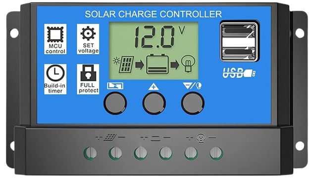
A Solar Charge Controller is an essential component in photovoltaic power systems. It manages the power going into the battery bank from the solar array. It ensures that the deep cycle batteries are not overcharged during the day, and that the power doesn’t run back to the solar panels overnight and drain the batteries. Some charge controllers also prevent battery over-discharge, protect from electrical overload, and display battery status and the flow of power.
Explore Projects Built with Solar Charge Controller
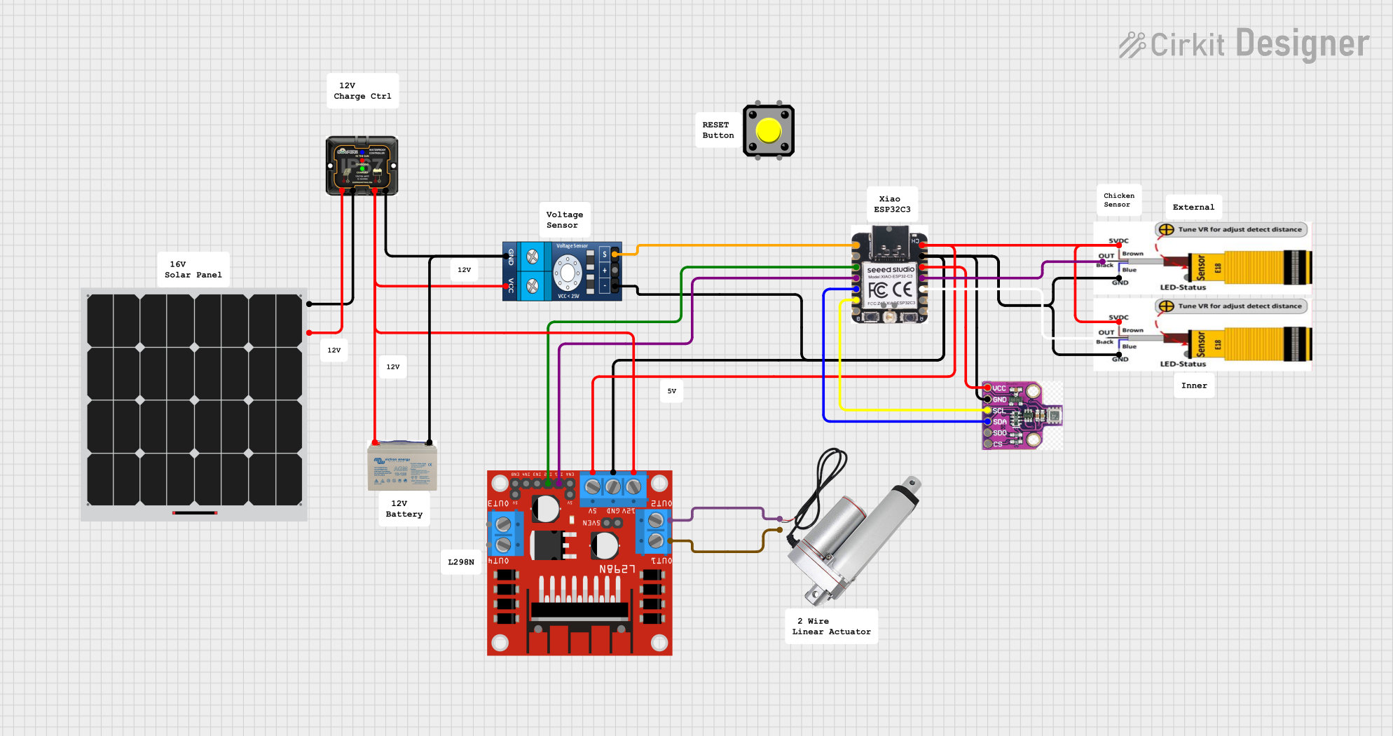
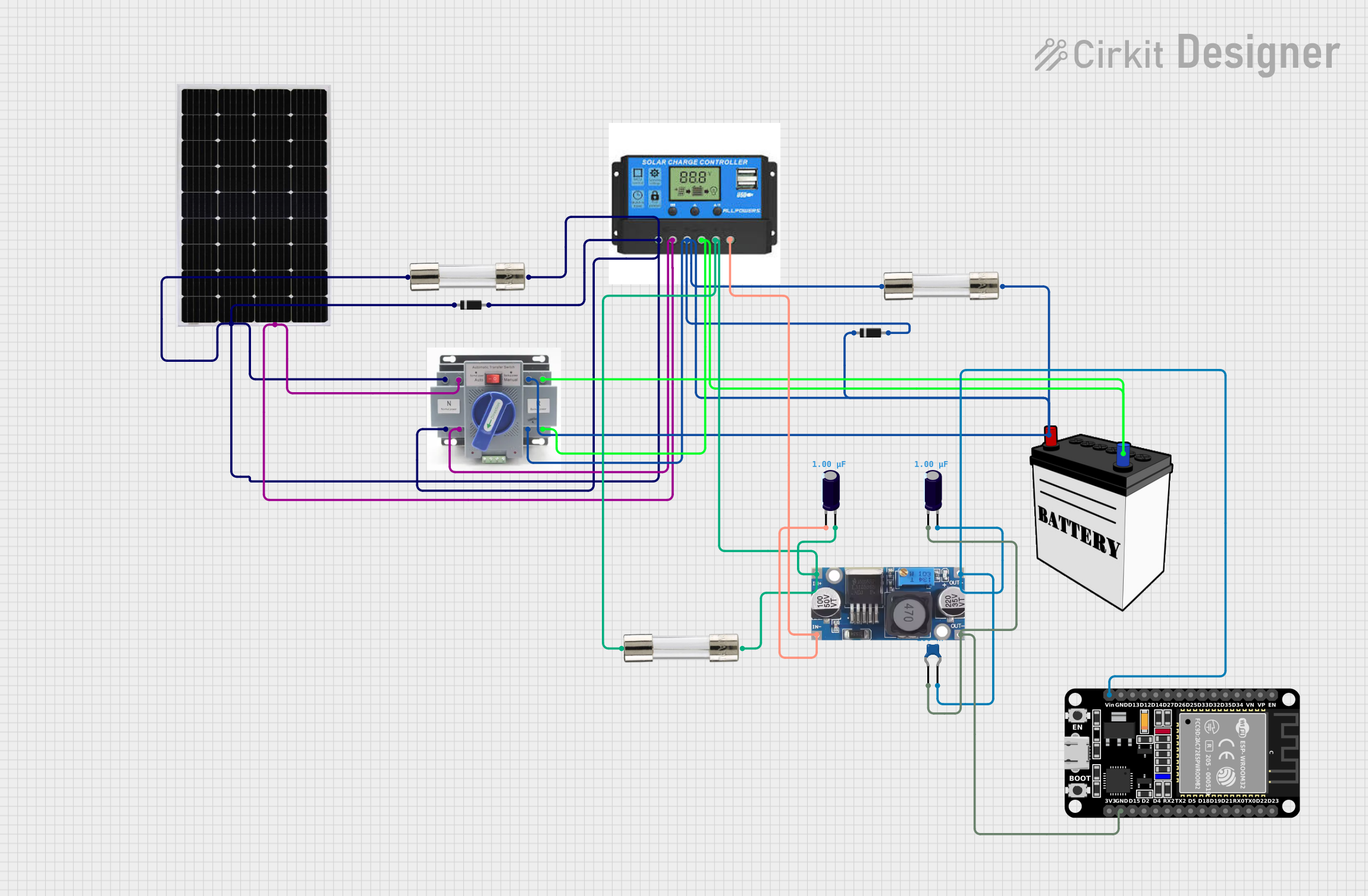
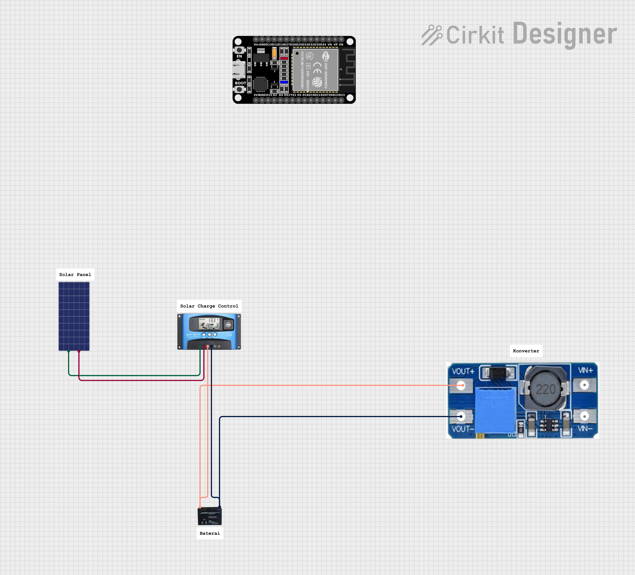
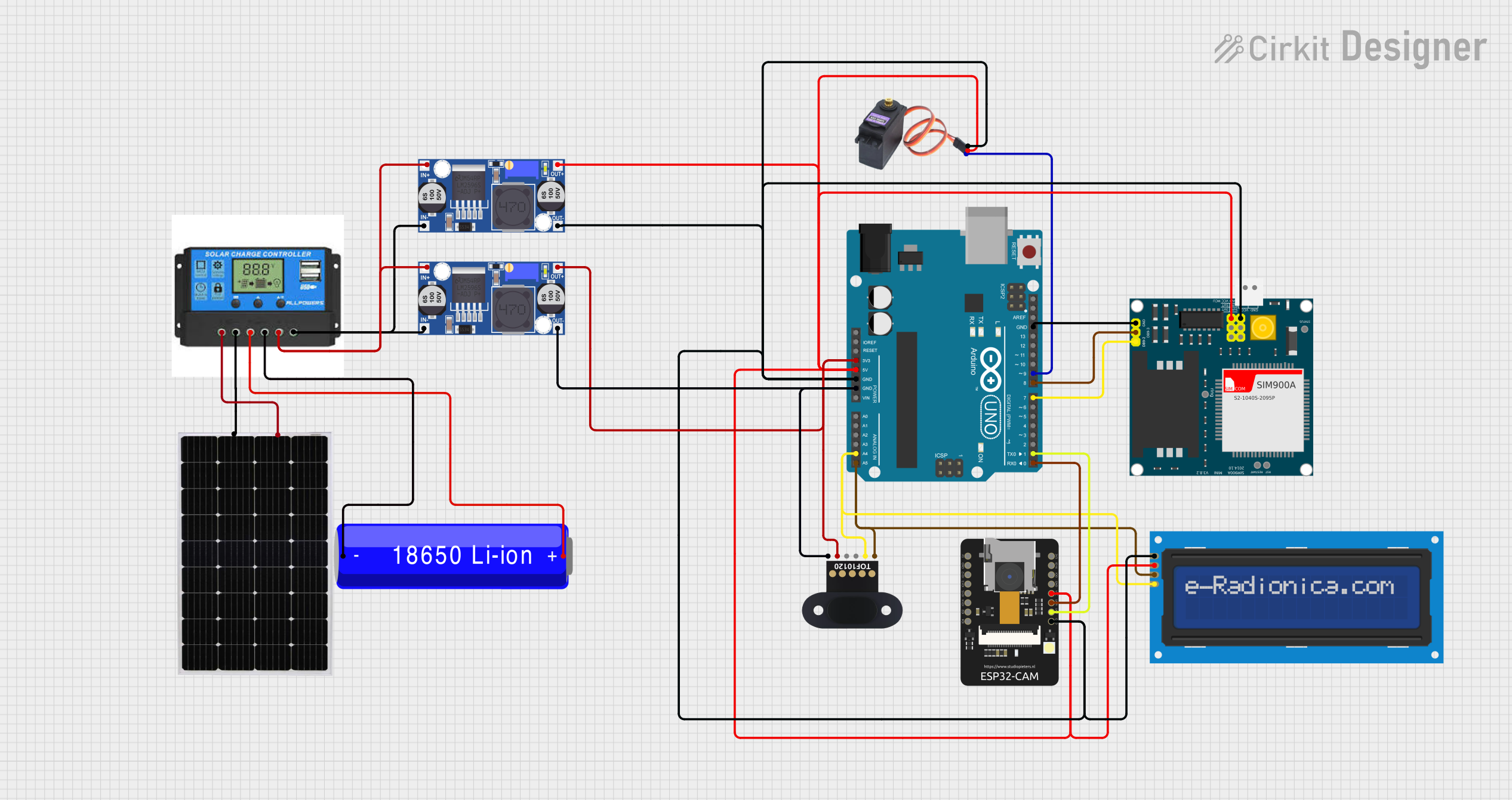
Explore Projects Built with Solar Charge Controller
Common Applications and Use Cases
- Off-grid solar power systems
- RV solar power systems
- Solar street lights
- Remote telecommunications equipment
- Any application where solar panels are used to charge a battery bank
Technical Specifications
Key Technical Details
- Rated Voltage: Typically 12V or 24V (auto-sensing)
- Maximum Charging Current: Depends on the model (e.g., 10A, 20A, 30A, etc.)
- Maximum Solar Input Voltage: Varies with model and design (e.g., 50V, 100V, 150V, etc.)
- Efficiency: >95% typically
- Self-consumption: <10mA
- Charge Control Modes: PWM (Pulse Width Modulation), MPPT (Maximum Power Point Tracking)
- Temperature Compensation: Included in some models
- Protections: Overcharge, over-discharge, overload, short circuit, and reverse polarity
Pin Configuration and Descriptions
| Pin/Port | Description |
|---|---|
| PV+ | Positive terminal for solar panel input |
| PV- | Negative terminal for solar panel input |
| BAT+ | Positive terminal for battery connection |
| BAT- | Negative terminal for battery connection |
| LOAD+ | Positive terminal for load connection |
| LOAD- | Negative terminal for load connection |
| TEMP | External temperature sensor input (if available) |
| COM | Communication port for monitoring (if available) |
Usage Instructions
How to Use the Component in a Circuit
- Connect the Battery: First, connect the battery to the charge controller - BAT+ and BAT- terminals. This is important to ensure the controller recognizes the system voltage.
- Connect the Solar Panels: Connect the solar panel to the PV+ and PV- terminals.
- Connect the Load: If applicable, connect the load to the LOAD+ and LOAD- terminals.
- Set the Charge Controller: Program the charge controller according to the type of battery and its specifications.
Important Considerations and Best Practices
- Always connect the battery first to allow the charge controller to recognize the system voltage.
- Ensure the solar panel voltage and current do not exceed the specifications of the charge controller.
- Use appropriate wire sizes to minimize voltage drop and prevent overheating.
- Install the charge controller in a cool, well-ventilated area.
- Regularly check connections to ensure they are tight and free from corrosion.
Troubleshooting and FAQs
Common Issues Users Might Face
- Battery not charging: Check connections, ensure the solar panel is receiving sunlight, and verify that the settings on the controller are correct for the type of battery.
- Controller not turning on: Verify the battery voltage is within the operating range of the controller.
- Overheating: Ensure the controller is in a well-ventilated area and not overloaded.
Solutions and Tips for Troubleshooting
- Battery Overcharging: Adjust the charge settings on the controller, or check if the temperature compensation is working if available.
- Battery Undercharging: Clean solar panels to ensure full exposure to sunlight, check for shading, and verify that the system voltage matches the battery bank.
- Load Not Working: Check the load wiring and ensure the load does not exceed the controller's maximum rating.
FAQs
- Q: Can I connect a wind turbine to my solar charge controller?
- A: No, solar charge controllers are designed for solar panels. Wind turbines require a different type of controller.
- Q: What is the difference between PWM and MPPT charge controllers?
- A: PWM controllers are simpler and lower cost but less efficient. MPPT controllers are more efficient and can utilize the solar panels more effectively, especially in varying light conditions.
Example Code for Arduino UNO Connection
// This example assumes the use of a PWM charge controller with a communication port
// connected to an Arduino UNO for monitoring purposes.

#include <SoftwareSerial.h>

SoftwareSerial solarSerial(10, 11); // RX, TX

void setup() {
  solarSerial.begin(9600); // Begin serial communication at 9600 baud rate
  Serial.begin(9600);     // Begin serial communication with computer
}

void loop() {
  if (solarSerial.available()) { // Check if data is available to read
    Serial.write(solarSerial.read()); // Send the data to the computer
  }
  if (Serial.available()) { // Check if data is available to write
    solarSerial.write(Serial.read()); // Send the data to the charge controller
  }
}
Note: The above code is a simple serial passthrough to allow communication between a computer and the solar charge controller. Actual implementation will depend on the specific model of the charge controller and the communication protocol it uses. Always refer to the manufacturer's manual for the correct communication setup and commands.