How to Use RFID Reader 830T for 125kHz and13.56MHz : Examples, Pinouts, and Specs
Introduction
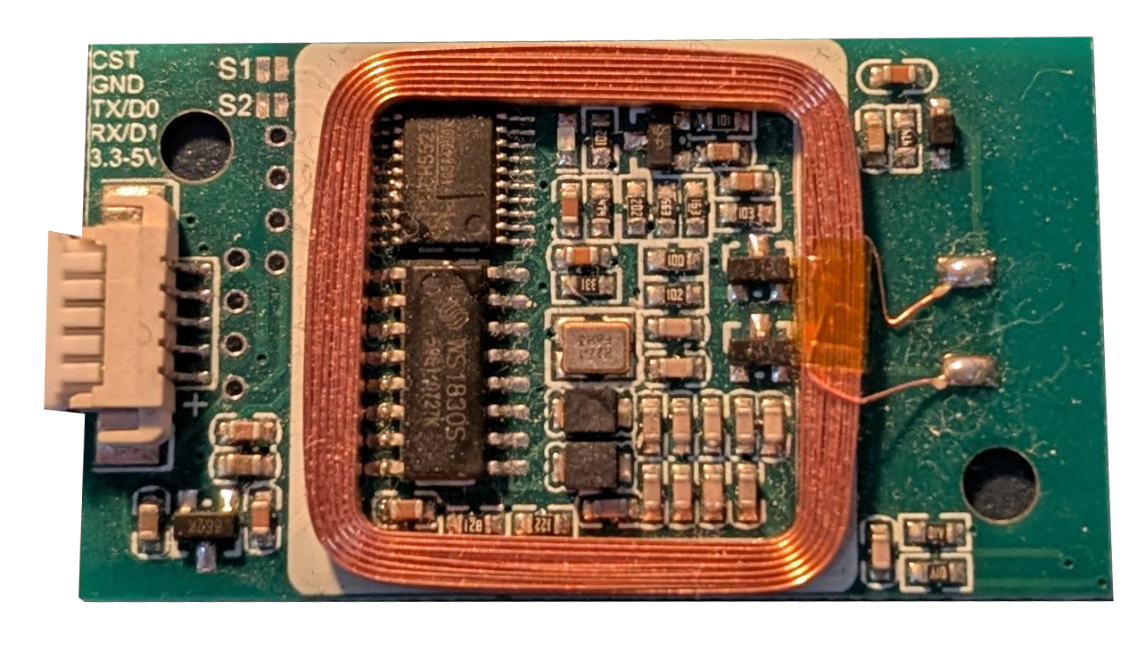
The RFID Reader 830T is a versatile and dual-frequency RFID reader capable of reading tags operating at both 125kHz (low frequency) and 13.56MHz (high frequency). This makes it suitable for a wide range of applications, including access control, inventory management, and identification systems. Its ability to support two widely used RFID frequencies ensures compatibility with a variety of RFID tags and systems.
Common applications and use cases:
- Access control systems for secure entry
- Inventory and asset tracking in warehouses
- Library book management systems
- Contactless payment systems
- Personal identification and authentication
Explore Projects Built with RFID Reader 830T for 125kHz and13.56MHz


Explore Projects Built with RFID Reader 830T for 125kHz and13.56MHz
Technical Specifications
The RFID Reader 830T is designed to provide reliable performance in various environments. Below are its key technical details:
General Specifications
| Parameter | Value |
|---|---|
| Operating Frequencies | 125kHz (LF), 13.56MHz (HF) |
| Communication Interface | UART (TTL), USB, or Wiegand |
| Operating Voltage | 5V DC |
| Current Consumption | < 100mA |
| Reading Distance | Up to 10cm (depending on tag) |
| Supported Protocols | ISO14443A, EM4100, MIFARE |
| Dimensions | 60mm x 40mm x 5mm |
| Operating Temperature | -20°C to +60°C |
Pin Configuration and Descriptions
The RFID Reader 830T typically uses a 6-pin interface for communication and power. Below is the pinout:
| Pin Number | Name | Description |
|---|---|---|
| 1 | VCC | Power supply input (5V DC) |
| 2 | GND | Ground connection |
| 3 | TX | UART Transmit (data output) |
| 4 | RX | UART Receive (data input) |
| 5 | Wiegand D0 | Wiegand Data 0 (optional interface) |
| 6 | Wiegand D1 | Wiegand Data 1 (optional interface) |
Usage Instructions
How to Use the RFID Reader 830T in a Circuit
- Power the Reader: Connect the
VCCpin to a 5V DC power source and theGNDpin to ground. - Establish Communication: Use the
TXandRXpins for UART communication with a microcontroller (e.g., Arduino UNO). Alternatively, use the Wiegand interface if your system supports it. - Place RFID Tag: Position the RFID tag within the reader's detection range (up to 10cm).
- Read Data: The reader will output the tag's unique ID via the selected communication interface.
Important Considerations and Best Practices
- Ensure the RFID tag is compatible with the reader's supported frequencies (125kHz or 13.56MHz).
- Avoid placing multiple tags within the reader's range simultaneously, as this may cause interference.
- Use proper decoupling capacitors near the power supply pins to minimize noise.
- If using the UART interface, ensure the baud rate matches the reader's default setting (typically 9600bps).
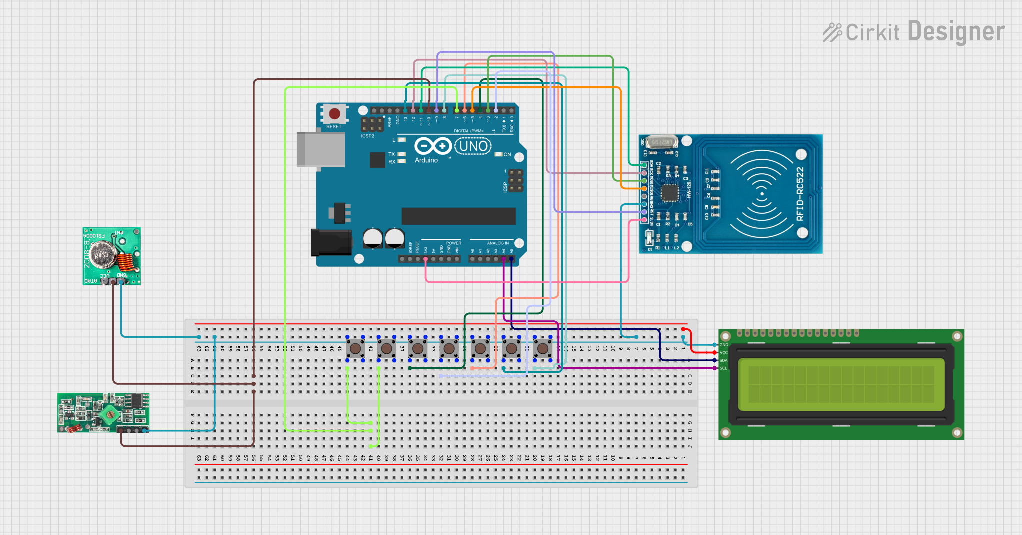
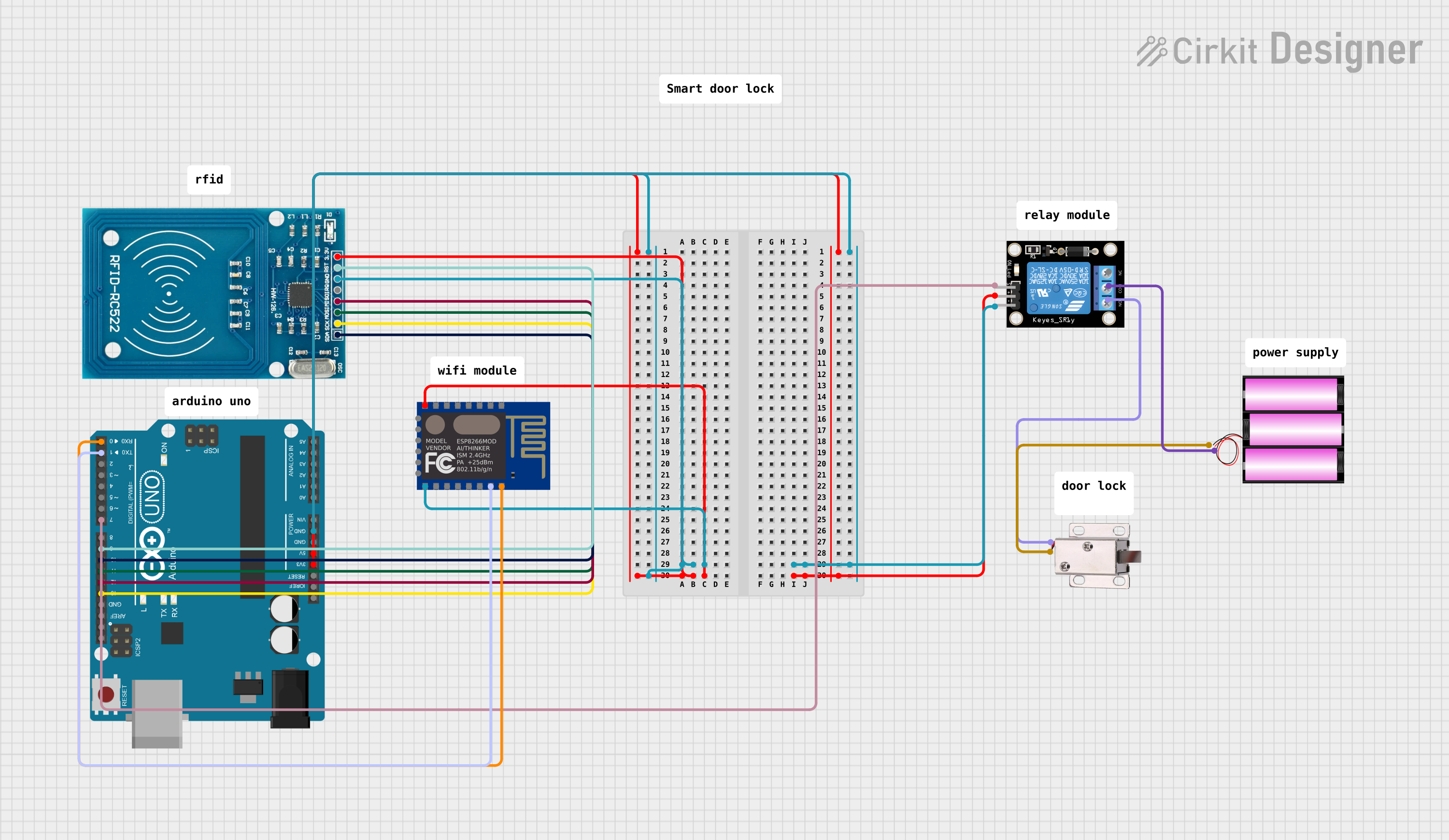
Example: Connecting to an Arduino UNO
Below is an example of how to connect and use the RFID Reader 830T with an Arduino UNO:
Wiring Diagram
| RFID Reader Pin | Arduino UNO Pin |
|---|---|
| VCC | 5V |
| GND | GND |
| TX | Pin 2 (RX) |
| RX | Pin 3 (TX) |
Arduino Code
#include <SoftwareSerial.h>

// Define RX and TX pins for SoftwareSerial
SoftwareSerial rfidReader(2, 3); // RX = Pin 2, TX = Pin 3

void setup() {
  Serial.begin(9600); // Initialize Serial Monitor
  rfidReader.begin(9600); // Initialize RFID reader communication
  Serial.println("RFID Reader 830T Initialized");
}

void loop() {
  // Check if data is available from the RFID reader
  if (rfidReader.available()) {
    String tagData = ""; // Variable to store tag data

    // Read data from the RFID reader
    while (rfidReader.available()) {
      char c = rfidReader.read();
      tagData += c; // Append each character to the tagData string
    }

    // Print the tag data to the Serial Monitor
    Serial.print("Tag ID: ");
    Serial.println(tagData);
  }
}
Notes:
- Ensure the RFID reader is powered before uploading the code to the Arduino.
- Use the Serial Monitor (set to 9600 baud) to view the tag ID when a tag is scanned.
Troubleshooting and FAQs
Common Issues and Solutions
No Data Output from the Reader
- Cause: Incorrect wiring or power supply.
- Solution: Double-check the connections, ensuring
VCCis connected to 5V andGNDto ground. Verify theTXandRXpins are correctly connected to the microcontroller.
Reader Not Detecting Tags
- Cause: Incompatible or damaged RFID tag.
- Solution: Ensure the tag operates at 125kHz or 13.56MHz. Test with a known working tag.
Interference or Unstable Readings
- Cause: Multiple tags in range or electrical noise.
- Solution: Remove additional tags from the reader's range. Add decoupling capacitors near the power supply pins.
Incorrect Data Displayed
- Cause: Baud rate mismatch or corrupted data.
- Solution: Verify the baud rate of the reader matches the microcontroller's settings (default is 9600bps). Check for loose connections.
FAQs
Q: Can the RFID Reader 830T read both 125kHz and 13.56MHz tags simultaneously?
A: No, the reader can only read one tag at a time. It automatically detects the frequency of the tag within its range.
Q: What is the maximum reading distance?
A: The maximum reading distance is up to 10cm, depending on the tag type and environmental conditions.
Q: Can I use the RFID Reader 830T with a Raspberry Pi?
A: Yes, the reader can be connected to a Raspberry Pi using the UART interface. Ensure proper voltage level shifting if required.
Q: Is the reader waterproof?
A: No, the RFID Reader 830T is not waterproof. Use it in a dry environment or enclose it in a protective casing for outdoor use.