
How to Use TB660 Stepper Motor Driver : Examples, Pinouts, and Specs
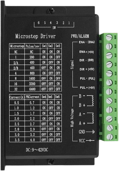
 Design with TB660 Stepper Motor Driver in Cirkit Designer
Introduction
The TB660 Stepper Motor Driver, manufactured by Tofelf (Part ID: B0BZYX7Z4Z), is a versatile and efficient driver designed for controlling stepper motors with precision. It supports adjustable current control, enabling compatibility with a wide range of stepper motor types. The TB660 is ideal for applications requiring smooth and accurate motor movement, such as 3D printers, CNC machines, robotics, and automated systems.
Explore Projects Built with TB660 Stepper Motor Driver
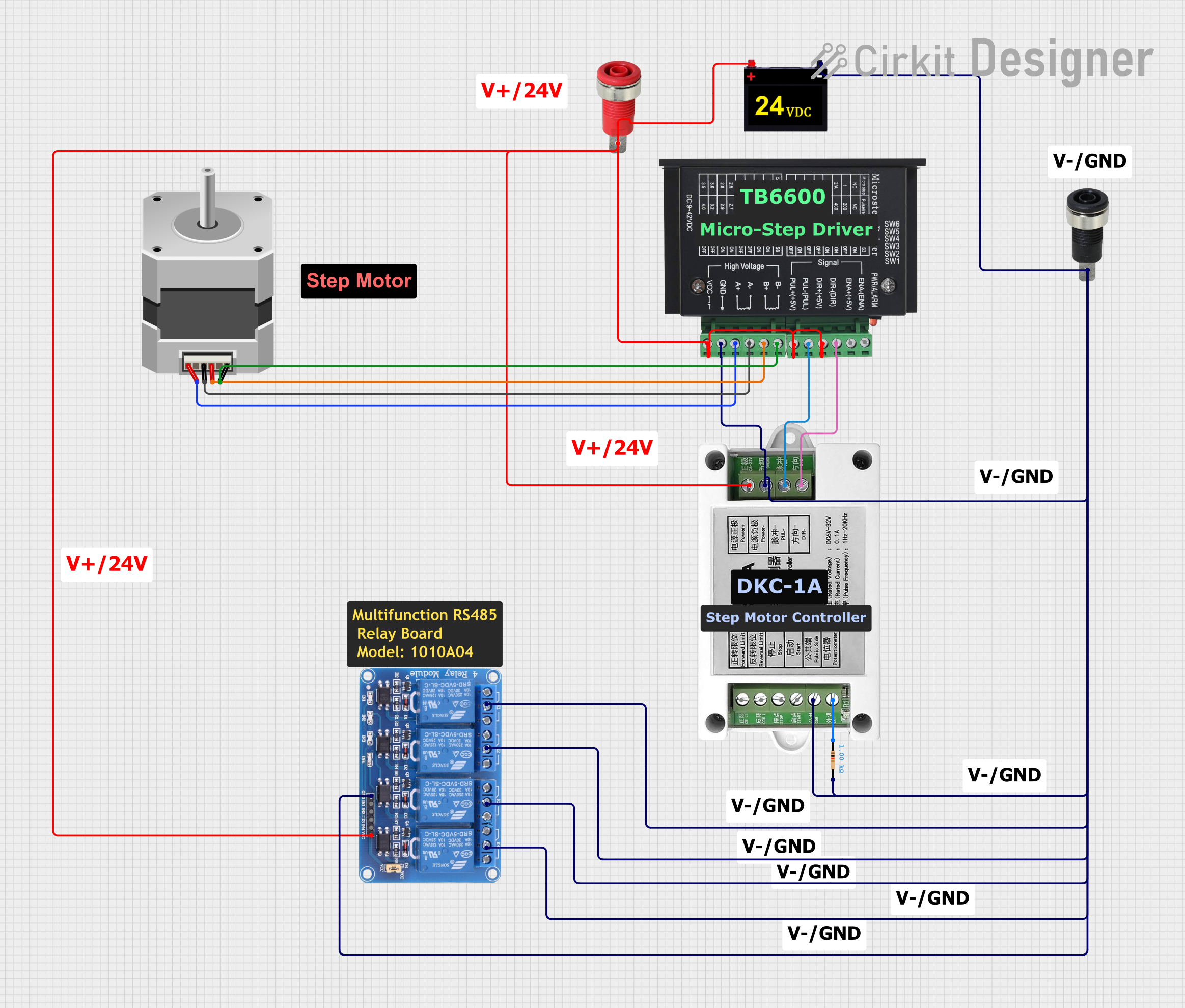 Open Project in Cirkit Designer
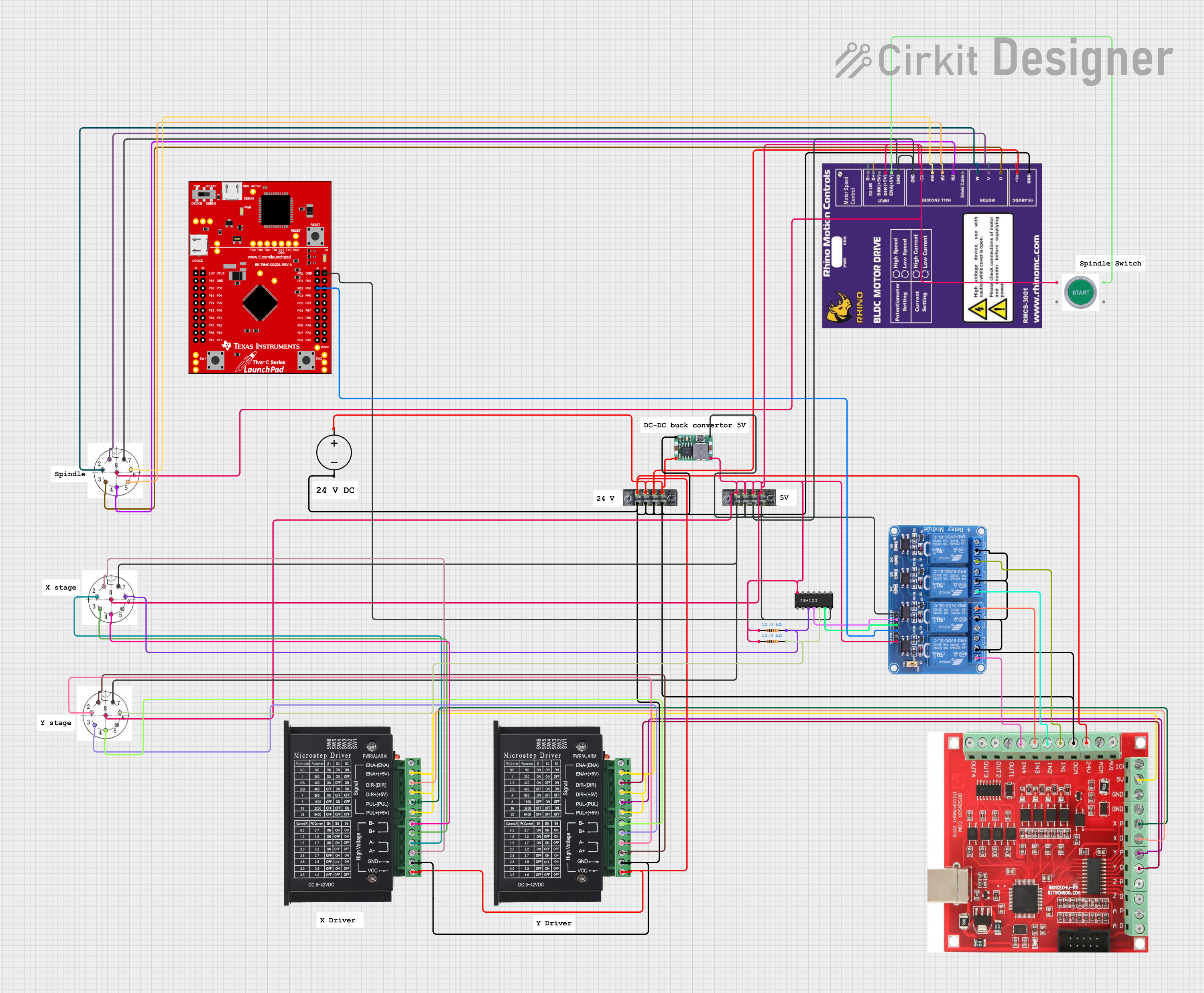 Open Project in Cirkit Designer
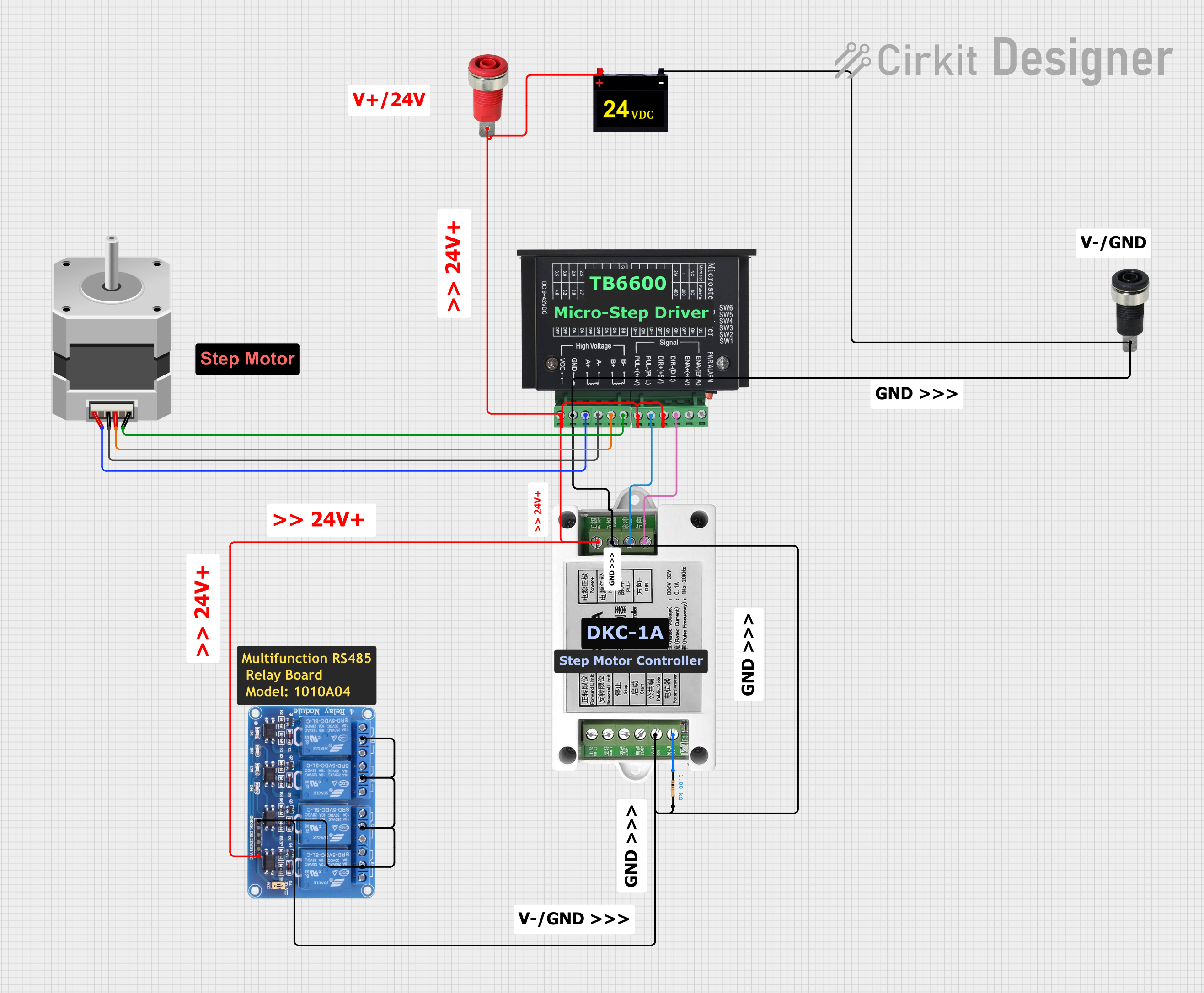 Open Project in Cirkit Designer
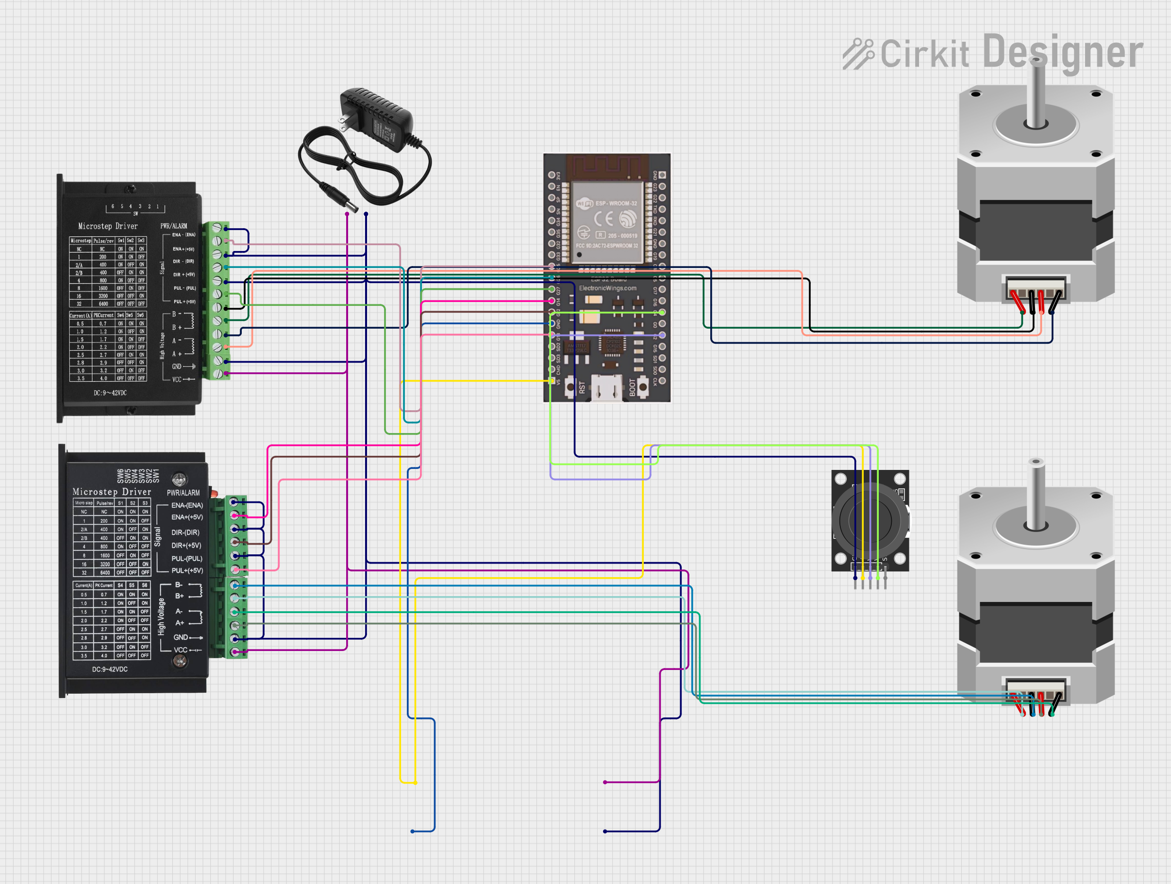 Open Project in Cirkit Designer
Explore Projects Built with TB660 Stepper Motor Driver
Open Project in Cirkit DesignerOpen Project in Cirkit DesignerOpen Project in Cirkit DesignerOpen Project in Cirkit DesignerCommon Applications:
- 3D printers for precise layer-by-layer movement
- CNC machines for accurate cutting and engraving
- Robotics for controlled motion
- Automated conveyor systems
- Camera sliders and gimbals
Technical Specifications
The TB660 Stepper Motor Driver is designed to provide reliable performance with the following key specifications:
| Parameter | Value |
|---|---|
| Operating Voltage (Vcc) | 4.5V to 5.5V |
| Motor Supply Voltage (VM) | 9V to 42V |
| Maximum Output Current | 4.5A (peak), 3.0A (continuous) |
| Microstepping Modes | Full, 1/2, 1/4, 1/8, 1/16 |
| Control Interface | Step and Direction signals |
| Logic Input Voltage | 2.0V (min) to 5.5V (max) |
| Operating Temperature | -20°C to +85°C |
| Dimensions | 20mm x 15mm x 5mm |
Pin Configuration and Descriptions
The TB660 Stepper Motor Driver has the following pinout:
| Pin Name | Pin Number | Description |
|---|---|---|
| VM | 1 | Motor power supply input (9V to 42V). |
| GND | 2 | Ground connection for both logic and motor power. |
| VCC | 3 | Logic power supply input (4.5V to 5.5V). |
| EN | 4 | Enable pin. Active LOW to enable the driver. |
| STEP | 5 | Step signal input. Each pulse advances the motor by one step. |
| DIR | 6 | Direction signal input. HIGH or LOW determines the motor's rotation direction. |
| MS1 | 7 | Microstepping mode selection pin 1. |
| MS2 | 8 | Microstepping mode selection pin 2. |
| MS3 | 9 | Microstepping mode selection pin 3. |
| OUT1A | 10 | Output for motor coil 1 (A+). |
| OUT1B | 11 | Output for motor coil 1 (A-). |
| OUT2A | 12 | Output for motor coil 2 (B+). |
| OUT2B | 13 | Output for motor coil 2 (B-). |
Usage Instructions
How to Use the TB660 in a Circuit
Power Connections:
- Connect the motor power supply (9V to 42V) to the
VMpin. - Connect the logic power supply (4.5V to 5.5V) to the
VCCpin. - Ensure a common ground connection between the motor power supply, logic power supply, and the
GNDpin.
- Connect the motor power supply (9V to 42V) to the
Motor Connections:
- Connect the stepper motor's coil wires to the
OUT1A,OUT1B,OUT2A, andOUT2Bpins. Refer to your motor's datasheet for the correct wiring.
- Connect the stepper motor's coil wires to the
Control Signals:
- Use the
STEPpin to send pulses for motor movement. Each pulse corresponds to one step. - Use the
DIRpin to set the motor's rotation direction (HIGH for clockwise, LOW for counterclockwise).
- Use the
Microstepping Configuration:
- Set the microstepping mode using the
MS1,MS2, andMS3pins. Refer to the table below for configuration:
- Set the microstepping mode using the
| MS1 | MS2 | MS3 | Microstepping Mode |
|---|---|---|---|
| LOW | LOW | LOW | Full Step |
| HIGH | LOW | LOW | 1/2 Step |
| HIGH | HIGH | LOW | 1/4 Step |
| HIGH | HIGH | HIGH | 1/16 Step |
- Enable/Disable:
- Pull the
ENpin LOW to enable the driver. Pull it HIGH to disable the driver.
- Pull the
Arduino UNO Example Code
Below is an example of how to control the TB660 Stepper Motor Driver using an Arduino UNO:
// Define pin connections
#define STEP_PIN 3  // Connect to the STEP pin of TB660
#define DIR_PIN 4   // Connect to the DIR pin of TB660
#define EN_PIN 5    // Connect to the EN pin of TB660

void setup() {
  pinMode(STEP_PIN, OUTPUT); // Set STEP pin as output
  pinMode(DIR_PIN, OUTPUT);  // Set DIR pin as output
  pinMode(EN_PIN, OUTPUT);   // Set EN pin as output

  digitalWrite(EN_PIN, LOW); // Enable the driver
}

void loop() {
  digitalWrite(DIR_PIN, HIGH); // Set direction to clockwise
  for (int i = 0; i < 200; i++) { // Rotate 200 steps (1 revolution for a 1.8° stepper)
    digitalWrite(STEP_PIN, HIGH); // Generate a step pulse
    delayMicroseconds(1000);      // Pulse duration
    digitalWrite(STEP_PIN, LOW);  // End of pulse
    delayMicroseconds(1000);      // Delay between steps
  }

  delay(1000); // Wait for 1 second

  digitalWrite(DIR_PIN, LOW); // Set direction to counterclockwise
  for (int i = 0; i < 200; i++) { // Rotate 200 steps in the opposite direction
    digitalWrite(STEP_PIN, HIGH);
    delayMicroseconds(1000);
    digitalWrite(STEP_PIN, LOW);
    delayMicroseconds(1000);
  }

  delay(1000); // Wait for 1 second
}
Important Considerations:
- Use a heatsink or cooling fan if the driver operates at high currents for extended periods.
- Ensure the motor power supply voltage matches the motor's rated voltage.
- Avoid disconnecting the motor while the driver is powered to prevent damage.
Troubleshooting and FAQs
Common Issues and Solutions
Motor Not Moving:
- Verify the power supply connections to
VMandVCC. - Check the
ENpin state (should be LOW to enable the driver). - Ensure the
STEPandDIRsignals are being sent correctly.
- Verify the power supply connections to
Motor Vibrates but Doesn't Rotate:
- Check the wiring of the motor coils. Incorrect connections can cause this issue.
- Verify the microstepping mode configuration.
Driver Overheating:
- Ensure proper cooling with a heatsink or fan.
- Reduce the motor current by adjusting the current control potentiometer (if available).
Motor Moves in the Wrong Direction:
- Reverse the connections of one motor coil (e.g., swap
OUT1AandOUT1B).
- Reverse the connections of one motor coil (e.g., swap
FAQs
Can I use the TB660 with a 12V stepper motor? Yes, as long as the motor's current rating is within the driver's limits.
What happens if I exceed the maximum current rating? The driver may overheat or enter thermal shutdown. Always stay within the specified limits.
Can I use the TB660 with a 24V power supply? Yes, the TB660 supports motor supply voltages up to 42V.
By following this documentation, you can effectively integrate the TB660 Stepper Motor Driver into your projects for precise and reliable motor control.