How to Use PWM motor speed controller: Examples, Pinouts, and Specs
Introduction
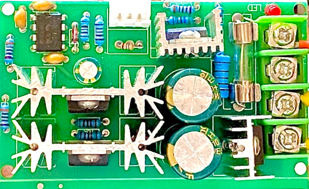
A PWM (Pulse Width Modulation) motor speed controller is an electronic device that regulates the speed of a DC motor by adjusting the pulse width of the input signal. By varying the duration of the "on" time in each pulse cycle, the controller effectively controls the average voltage delivered to the motor, thus controlling its speed. PWM controllers are favored for their efficiency, as they minimize power loss by switching transistors between fully on and fully off states, rather than operating in their resistive region.
Explore Projects Built with PWM motor speed controller


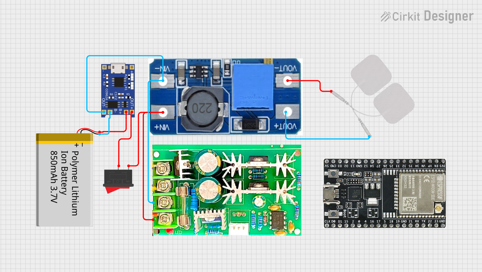
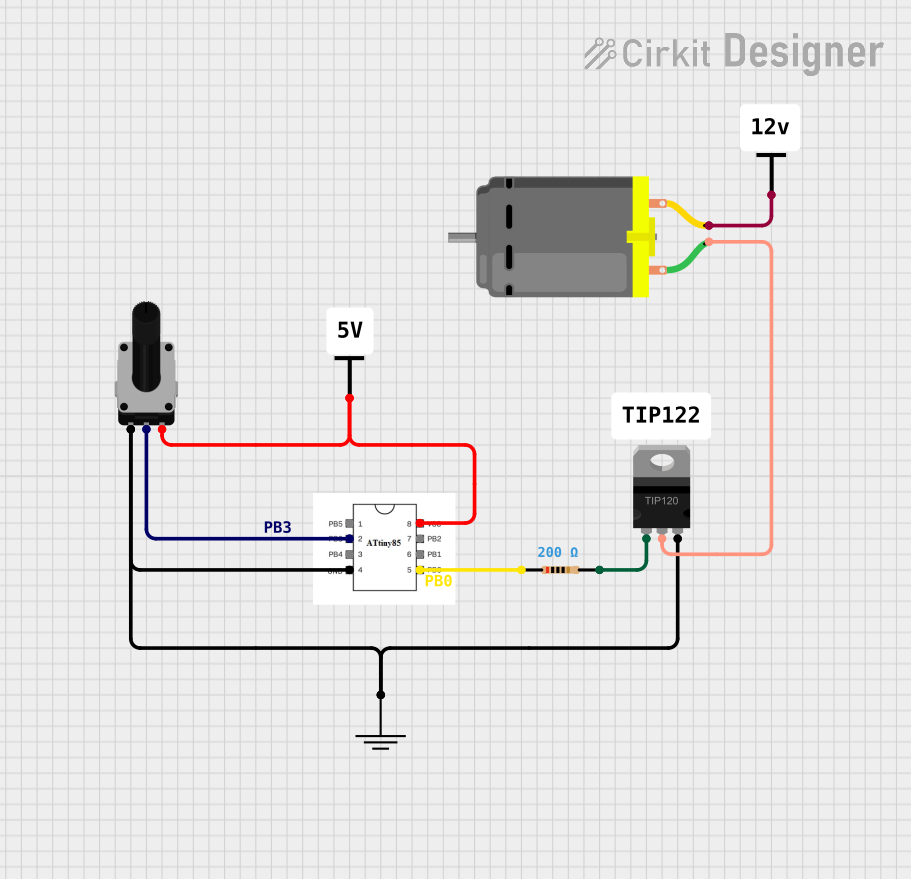
Explore Projects Built with PWM motor speed controller
Common Applications and Use Cases
- Robotics: Precise motor control for movement and positioning.
- Consumer Electronics: Speed control in devices like fans, drills, and toys.
- Automotive: Controlling the speed of DC motors in electric vehicles.
- Industrial Automation: Conveyor systems, pumps, and process control systems.
Technical Specifications
Key Technical Details
- Operating Voltage Range: Typically 3V to 60V DC
- Current Rating: Up to 20A (varies by model)
- Frequency Range: 1kHz to 25kHz (model specific)
- Efficiency: Typically > 95%
- Control Method: PWM based on potentiometer input or digital signal
Pin Configuration and Descriptions
| Pin Number | Name | Description |
|---|---|---|
| 1 | Vcc | Connect to the positive terminal of the power supply |
| 2 | GND | Connect to the ground of the power supply |
| 3 | OUT+ | Connect to the positive terminal of the motor |
| 4 | OUT- | Connect to the negative terminal of the motor |
| 5 | PWM | PWM signal input (optional for external control) |
| 6 | VR | Connect to the wiper of the potentiometer for speed control |
Usage Instructions
How to Use the Component in a Circuit
- Connect the power supply to the Vcc and GND pins of the controller.
- Attach the motor to the OUT+ and OUT- terminals.
- For manual speed control, connect a potentiometer to the VR pin.
- (Optional) For digital control, apply a PWM signal to the PWM input pin.
Important Considerations and Best Practices
- Ensure the power supply voltage and current do not exceed the controller's ratings.
- Use a heat sink if the controller is expected to handle currents near its maximum rating.
- Keep the PWM frequency within the specified range for optimal performance.
- Use appropriate wire gauge for connections to handle the expected current.
- Protect the circuit with a fuse or circuit breaker to prevent damage from overcurrent conditions.
Troubleshooting and FAQs
Common Issues
- Motor not spinning: Check connections, power supply, and ensure the potentiometer is not set to minimum.
- Motor speed not changing: Verify the PWM signal is within the correct frequency and duty cycle range.
- Overheating: Ensure adequate cooling and that the current draw is within specifications.
Solutions and Tips for Troubleshooting
- Double-check wiring and solder joints for any loose connections or shorts.
- Measure the input voltage and current to ensure they match the controller's requirements.
- Use an oscilloscope to verify the PWM signal's frequency and duty cycle.
- If using a microcontroller, ensure the code is generating the correct PWM output.
FAQs
Q: Can I control the motor speed using an Arduino? A: Yes, you can use an Arduino to generate a PWM signal to control the motor speed.
Q: What is the maximum motor size I can control with this device? A: It depends on the specific model's current rating. Check the technical specifications for the maximum current rating.
Q: Can I use this controller with an AC motor? A: No, this controller is designed for DC motors only.
Example Code for Arduino UNO
// Define the PWM pin connected to the PWM input of the controller
const int pwmPin = 3; // Must be a PWM-capable pin

void setup() {
  // Set the PWM pin as an output
  pinMode(pwmPin, OUTPUT);
}

void loop() {
  // Increase motor speed gradually
  for (int dutyCycle = 0; dutyCycle <= 255; dutyCycle++) {
    analogWrite(pwmPin, dutyCycle);
    delay(10); // Short delay to observe speed change
  }

  // Decrease motor speed gradually
  for (int dutyCycle = 255; dutyCycle >= 0; dutyCycle--) {
    analogWrite(pwmPin, dutyCycle);
    delay(10); // Short delay to observe speed change
  }
}
Note: The analogWrite function on Arduino UNO uses a default frequency of approximately 490Hz for pins 3, 9, 10, and 11, and 980Hz for pins 5 and 6. Ensure that the PWM frequency is compatible with your motor controller.
This documentation provides a comprehensive guide to using a PWM motor speed controller. For further assistance, consult the manufacturer's datasheet or contact technical support.