How to Use 8bit led bar: Examples, Pinouts, and Specs
Introduction
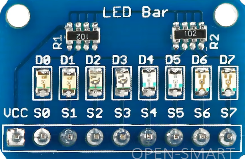
An 8-bit LED bar is a visual display component that consists of a series of 8 LEDs arranged in a linear bar format. Each LED in the bar corresponds to a single bit, allowing the display of binary values or levels in a compact and easily readable manner. The LEDs can be individually controlled to represent data, levels, or status indicators in various applications.
Explore Projects Built with 8bit led bar
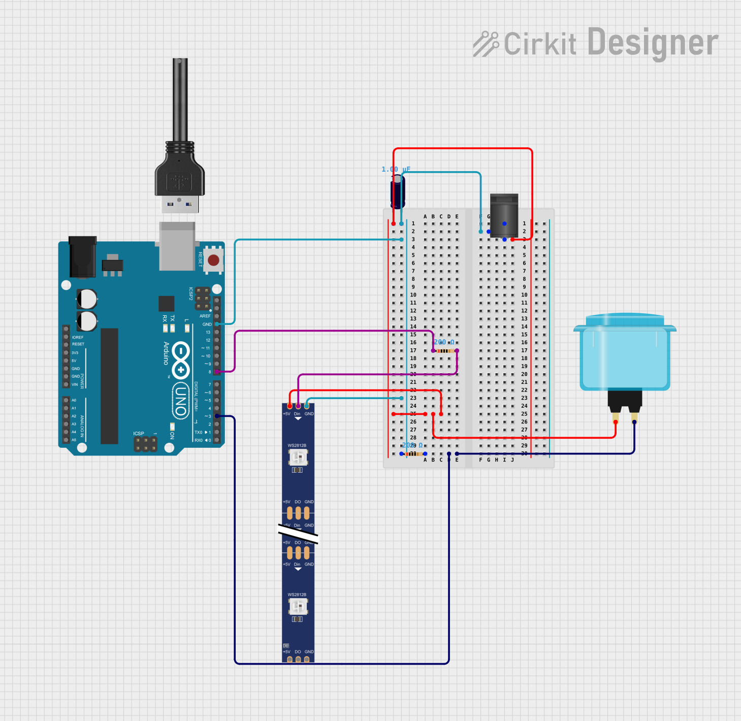
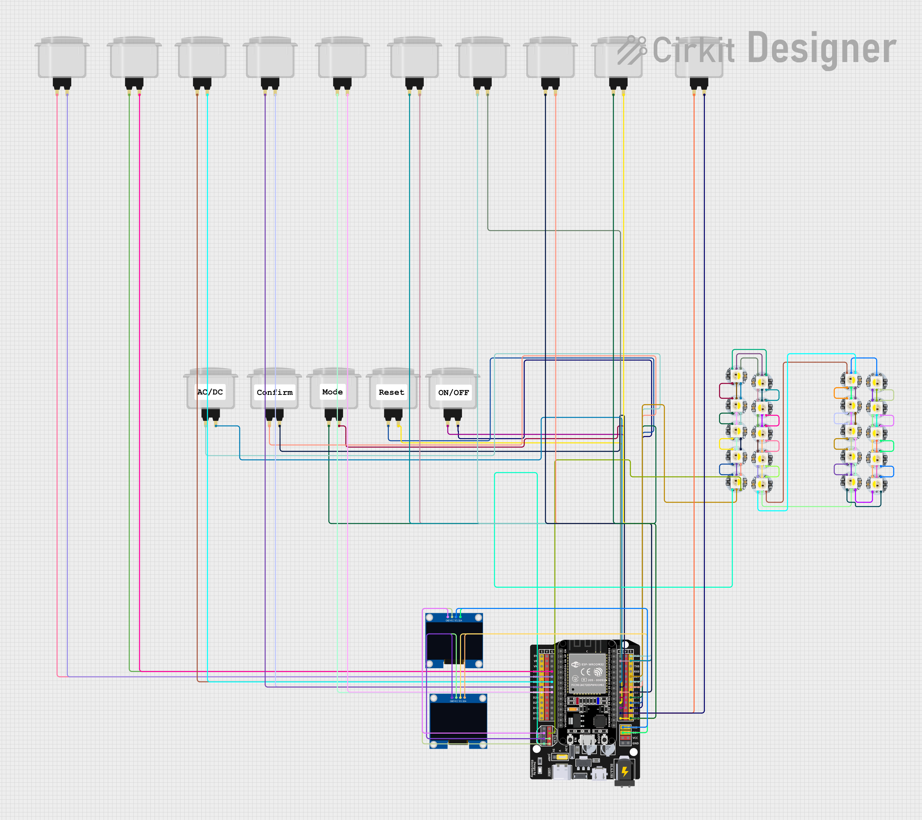
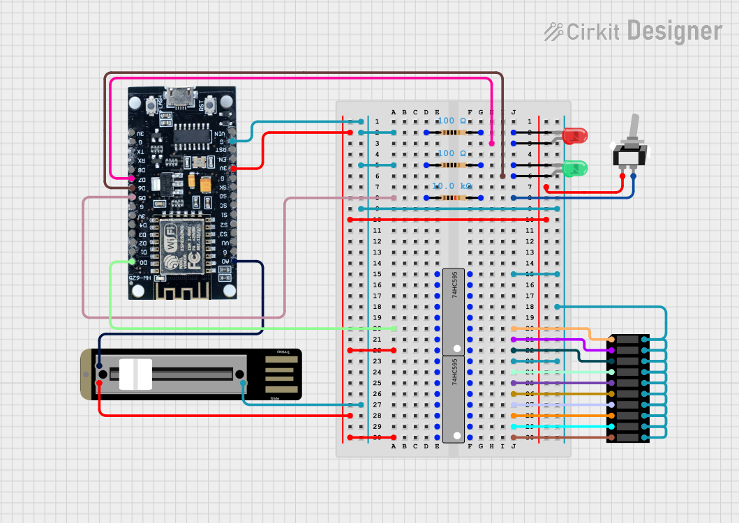
Explore Projects Built with 8bit led bar
Common Applications and Use Cases
- Visual representation of binary data
- Audio level meters (VU meters)
- Battery level indicators
- Progress bars in embedded systems
- Debugging tools for microcontroller outputs
Technical Specifications
The 8-bit LED bar is typically designed for easy integration into electronic circuits. Below are the key technical details:
General Specifications
| Parameter | Value |
|---|---|
| Number of LEDs | 8 |
| Operating Voltage | 2.0V - 3.3V per LED (typical) |
| Forward Current (per LED) | 20mA (maximum) |
| LED Color | Red, Green, or Multicolor |
| Dimensions | Varies (e.g., 50mm x 10mm) |
| Mounting Type | Through-hole or SMD |
Pin Configuration and Descriptions
The 8-bit LED bar typically has 10 pins: 8 for the individual LEDs and 2 for the common cathode or anode (depending on the configuration). Below is the pinout for a common cathode configuration:
| Pin Number | Description |
|---|---|
| 1 | LED 1 Anode |
| 2 | LED 2 Anode |
| 3 | LED 3 Anode |
| 4 | LED 4 Anode |
| 5 | LED 5 Anode |
| 6 | LED 6 Anode |
| 7 | LED 7 Anode |
| 8 | LED 8 Anode |
| 9 | Common Cathode (-) |
| 10 | Common Cathode (-) (optional) |
Note: For common anode configurations, the cathodes of the LEDs are connected to individual pins, and the anode is shared.
Usage Instructions
How to Use the 8-Bit LED Bar in a Circuit
- Power Supply: Ensure the LEDs are powered within their operating voltage range (2.0V - 3.3V per LED). Use current-limiting resistors (typically 220Ω to 1kΩ) in series with each LED to prevent overcurrent.
- Connection: Connect the anodes (or cathodes, depending on the configuration) of the LEDs to the control pins of your microcontroller or driver circuit.
- Control: Use GPIO pins of a microcontroller to control the LEDs. Set the pins HIGH or LOW to turn the LEDs ON or OFF, respectively.
Important Considerations and Best Practices
- Current Limiting: Always use resistors to limit the current through each LED. Failure to do so may damage the LEDs.
- Brightness Control: Use Pulse Width Modulation (PWM) to control the brightness of the LEDs.
- Heat Management: Avoid driving all LEDs at maximum current for extended periods to prevent overheating.
- Common Cathode vs. Common Anode: Verify the configuration of your LED bar before connecting it to a circuit.
Example: Connecting to an Arduino UNO
Below is an example of how to connect and control an 8-bit LED bar using an Arduino UNO:
Circuit Diagram
- Connect pins 1-8 of the LED bar to Arduino digital pins 2-9.
- Connect the common cathode pins (9 and 10) to GND.
- Place a 220Ω resistor in series with each LED.
Arduino Code
// Define the pins connected to the LED bar
const int ledPins[] = {2, 3, 4, 5, 6, 7, 8, 9};

void setup() {
  // Set all LED pins as OUTPUT
  for (int i = 0; i < 8; i++) {
    pinMode(ledPins[i], OUTPUT);
  }
}

void loop() {
  // Turn on LEDs one by one
  for (int i = 0; i < 8; i++) {
    digitalWrite(ledPins[i], HIGH); // Turn on the LED
    delay(200);                     // Wait for 200ms
    digitalWrite(ledPins[i], LOW);  // Turn off the LED
  }
}
Note: Modify the delay() value to adjust the speed of the LED sequence.
Troubleshooting and FAQs
Common Issues and Solutions
LEDs Not Lighting Up
- Cause: Incorrect wiring or missing current-limiting resistors.
- Solution: Double-check the wiring and ensure resistors are in place.
Dim LEDs
- Cause: Insufficient current or high-value resistors.
- Solution: Use resistors with lower resistance (e.g., 220Ω).
Flickering LEDs
- Cause: Unstable power supply or incorrect PWM settings.
- Solution: Use a stable power source and verify PWM frequency.
Overheating
- Cause: Excessive current through the LEDs.
- Solution: Ensure resistors are properly sized to limit current.
FAQs
Q: Can I use the 8-bit LED bar with a 5V power supply?
A: Yes, but you must use appropriate resistors to limit the current through each LED.
Q: How do I control the brightness of the LEDs?
A: Use PWM signals from your microcontroller to adjust the brightness.
Q: Can I use the LED bar with a shift register?
A: Yes, a shift register like the 74HC595 can be used to control the LEDs with fewer GPIO pins.
Q: What happens if I connect the LEDs without resistors?
A: The LEDs may draw excessive current, leading to damage or failure.
By following this documentation, you can effectively integrate and troubleshoot an 8-bit LED bar in your projects.