How to Use Adafruit Quad AlphaNumeric Featherwing - Pure Green: Examples, Pinouts, and Specs
Introduction
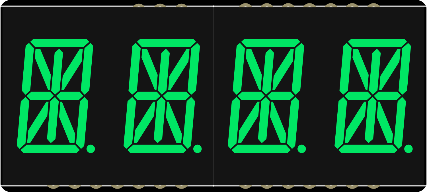
The Adafruit Quad AlphaNumeric Featherwing is a versatile and easy-to-use LED matrix display board that is designed to work with the Feather ecosystem. It features four 14-segment alphanumeric displays capable of showing text, numbers, and symbols in a bright pure green color. This component is ideal for adding a user interface to projects without the need for a full graphical display, making it perfect for time displays, counters, and readouts in various electronics projects.
Explore Projects Built with Adafruit Quad AlphaNumeric Featherwing - Pure Green
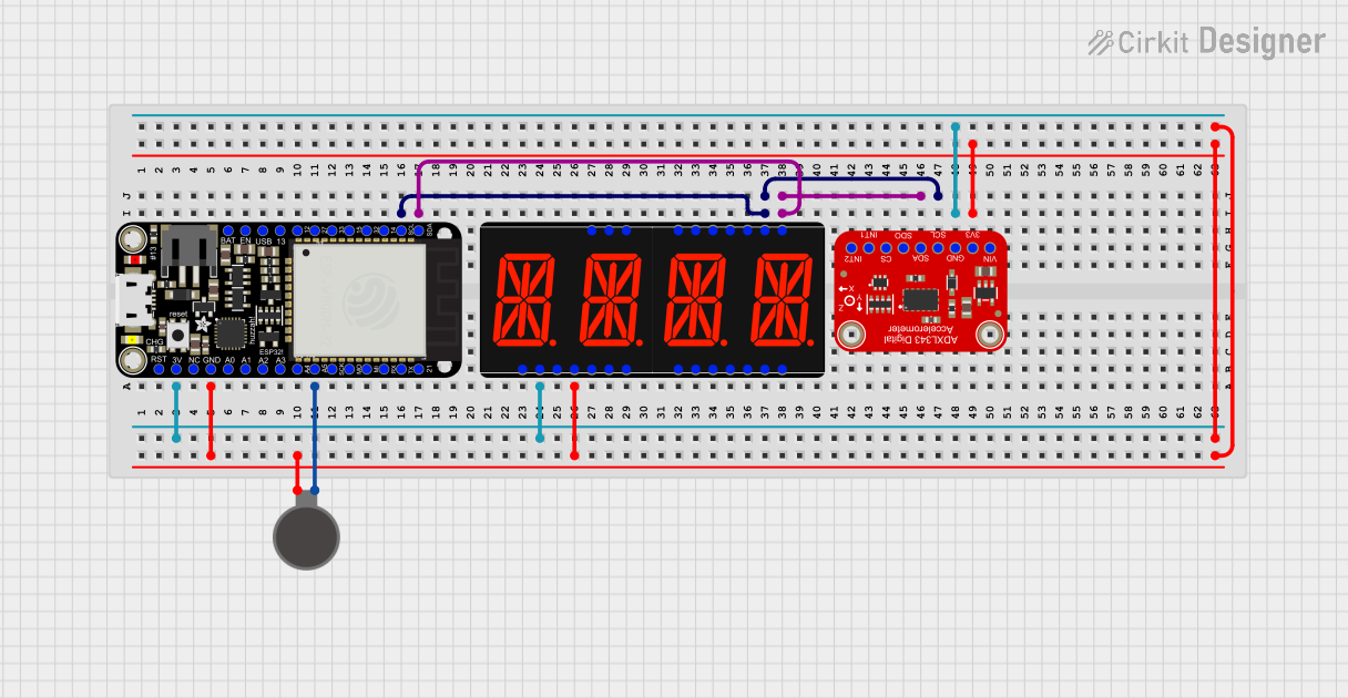


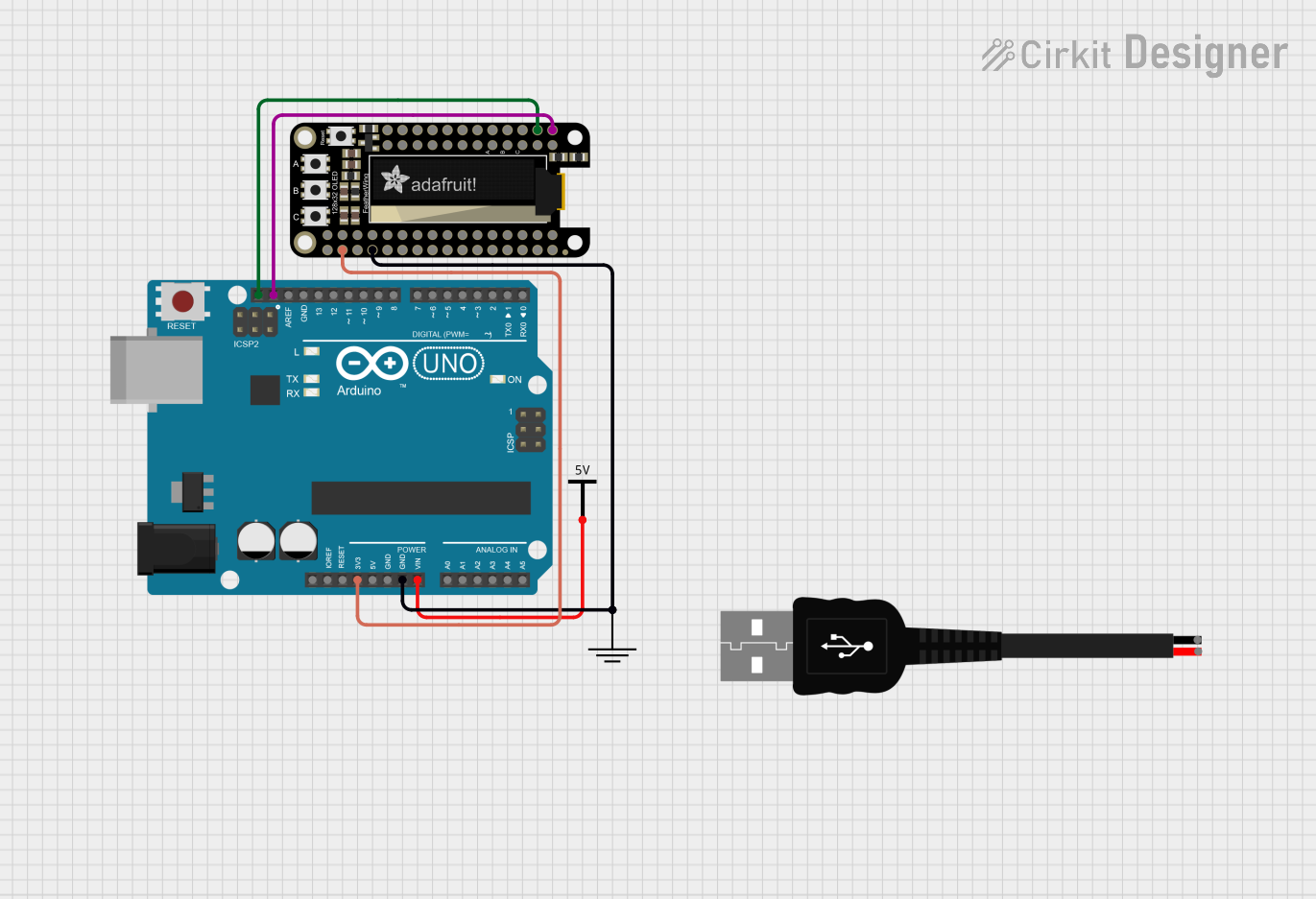
Explore Projects Built with Adafruit Quad AlphaNumeric Featherwing - Pure Green
Common Applications and Use Cases
- Clocks and timers
- Counter displays
- Scoreboards
- Message boards
- Data monitoring displays
Technical Specifications
Key Technical Details
- Operating Voltage: 3.3V to 5V
- Current Draw: 80mA (typical, with all segments lit)
- Display Color: Pure Green
- Number of Characters: 4
- Character Height: 0.54 inches
- Communication: I2C interface
Pin Configuration and Descriptions
| Pin Number | Name | Description |
|---|---|---|
| 1 | GND | Ground pin, common reference for all circuitry |
| 2 | VCC | Power supply pin (3.3V to 5V) |
| 3 | SDA | I2C Data line |
| 4 | SCL | I2C Clock line |
| 5 | RST | Reset pin (optional use) |
Usage Instructions
How to Use the Component in a Circuit
Powering the Display:
- Connect the VCC pin to a 3.3V or 5V power supply.
- Connect the GND pin to the ground of the power supply.
Interfacing with a Microcontroller:
- Connect the SDA and SCL pins to the I2C data and clock lines of your microcontroller, respectively.
- If necessary, connect the RST pin to a digital output on your microcontroller for resetting the display.
Programming the Display:
- Use the Adafruit LED Backpack library to control the display via I2C.
- Initialize the display and set the brightness as needed.
Important Considerations and Best Practices
- Ensure that the power supply voltage does not exceed the maximum rating of 5V.
- When displaying static text for extended periods, consider using a lower brightness setting to prolong the life of the LEDs.
- Use pull-up resistors on the I2C lines if they are not already present on the microcontroller board.
- Avoid exposing the display to mechanical stress or extreme temperatures.
Example Code for Arduino UNO
#include <Wire.h>
#include <Adafruit_LEDBackpack.h>
#include <Adafruit_GFX.h>

Adafruit_AlphaNum4 alpha4 = Adafruit_AlphaNum4();

void setup() {
  alpha4.begin(0x70);  // Initialize the display with the I2C address 0x70
  alpha4.setBrightness(10);  // Set the display brightness (0 is dimmest, 15 is brightest)
}

void loop() {
  alpha4.writeDigitAscii(0, 'A');  // Display 'A' on the first character position
  alpha4.writeDigitAscii(1, 'd');  // Display 'd' on the second character position
  alpha4.writeDigitAscii(2, 'a');  // Display 'a' on the third character position
  alpha4.writeDigitAscii(3, 'F');  // Display 'F' on the fourth character position
  alpha4.writeDisplay();           // Send the data to the display to actually show it
  delay(1000);                     // Wait for a second
  alpha4.clear();                  // Clear the display
  alpha4.writeDisplay();           // Update the display to show the clear
  delay(1000);                     // Wait for a second
}
Troubleshooting and FAQs
Common Issues
Display Not Lighting Up:
- Check the power connections to ensure the display is properly powered.
- Verify that the I2C address used in the code matches the address of the display.
- Ensure that the I2C lines are connected correctly and that pull-up resistors are in place if needed.
Characters Not Displaying Correctly:
- Check for any loose connections or soldering issues.
- Make sure the correct characters are being sent in the code.
- Verify that the library and code are compatible with the display.
Solutions and Tips for Troubleshooting
- Use the
i2cdetecttool or similar to confirm that the display is detected on the I2C bus. - If using multiple I2C devices, ensure that there are no address conflicts.
- Check the Arduino serial monitor for any error messages or debug information.
- Review the Adafruit LED Backpack library documentation for additional functions and examples.
FAQs
Q: Can I use this display with a 5V microcontroller like the Arduino UNO? A: Yes, the display can be used with both 3.3V and 5V microcontrollers.
Q: How do I change the I2C address of the display? A: The I2C address can be changed by soldering the address jumpers on the back of the PCB. Refer to the Adafruit guide for the specific jumper settings.
Q: Can I daisy-chain multiple displays together? A: Yes, multiple displays can be connected in series via the I2C bus, with unique addresses set for each display.
Q: Is it possible to display custom characters or symbols? A: Yes, the display supports custom characters and symbols by setting individual segments. Refer to the Adafruit GFX library for creating custom characters.