How to Use Autogate Transformer: Examples, Pinouts, and Specs
Introduction
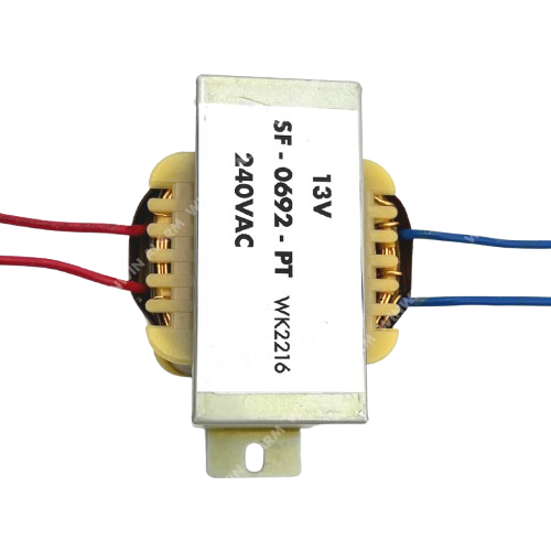
The Autogate Transformer is a specialized transformer designed for use in automated gate systems. Its primary function is to step down or step up voltage levels to ensure efficient power distribution and control. This component is essential for providing the correct voltage to motors, sensors, and control units in autogate systems, ensuring smooth and reliable operation.
Explore Projects Built with Autogate Transformer
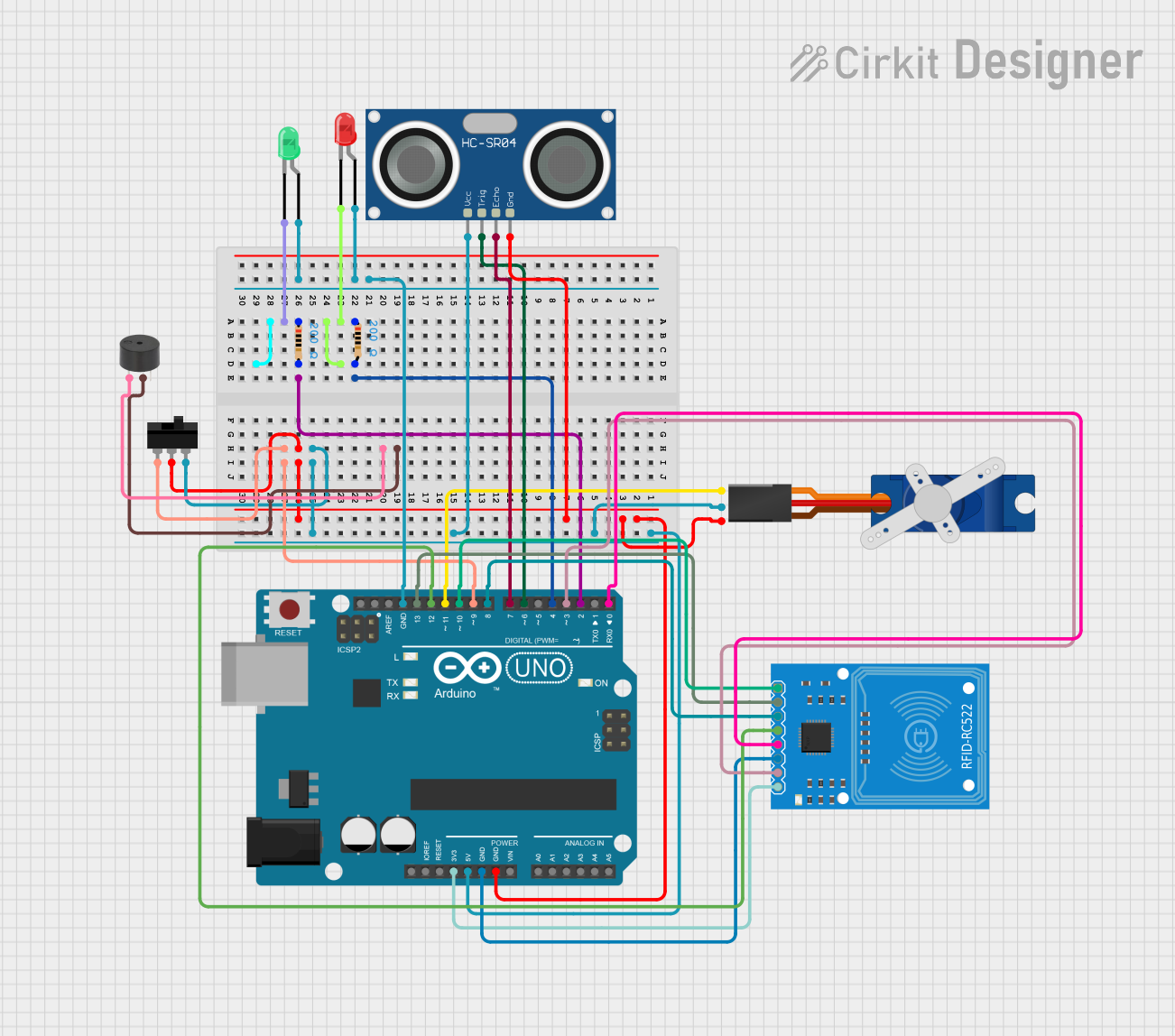

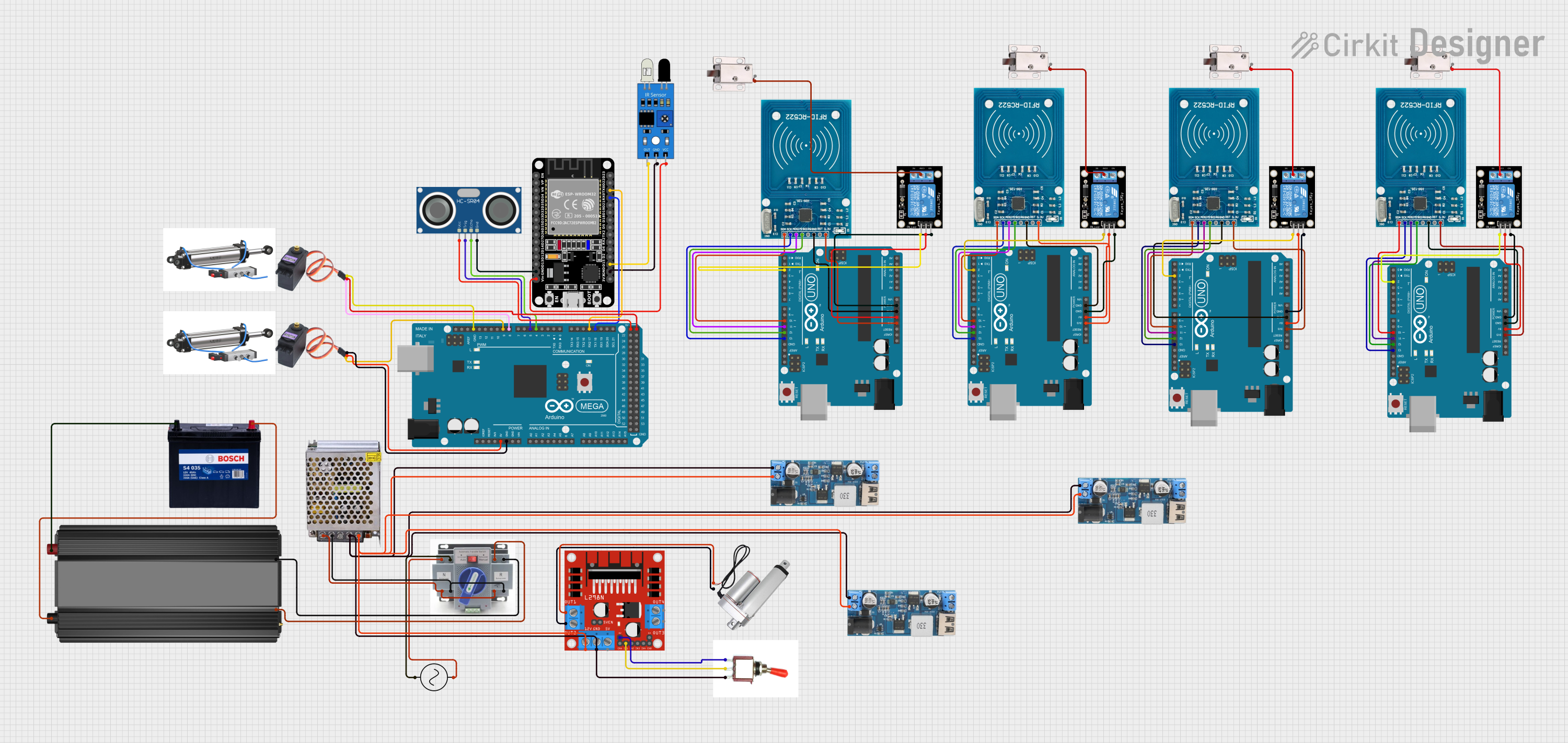

Explore Projects Built with Autogate Transformer
Common Applications and Use Cases
- Powering automated gate motors and control circuits.
- Voltage regulation for sensors and safety mechanisms in autogate systems.
- Ensuring stable power delivery in residential and commercial gate automation setups.
Technical Specifications
Key Technical Details
- Input Voltage: 220V AC (typical for residential systems) or 110V AC (depending on region).
- Output Voltage: 12V AC or 24V AC (depending on the model).
- Power Rating: 50W to 200W (varies by model).
- Frequency: 50Hz or 60Hz.
- Insulation Class: Class B or higher for safety and durability.
- Efficiency: ≥ 85% under nominal load conditions.
- Operating Temperature: -10°C to 50°C.
Pin Configuration and Descriptions
The Autogate Transformer typically has two sets of terminals: one for the primary (input) side and one for the secondary (output) side. Below is a table describing the pin configuration:
| Pin Number | Label | Description |
|---|---|---|
| 1 | L (Live) | Live input for AC mains voltage (e.g., 220V AC). |
| 2 | N (Neutral) | Neutral input for AC mains voltage. |
| 3 | GND (Ground) | Ground connection for safety. |
| 4 | Vout+ | Positive output terminal (e.g., 12V AC or 24V AC). |
| 5 | Vout- | Negative output terminal (e.g., 12V AC or 24V AC). |
Note: Always refer to the specific model's datasheet for exact pin configurations.
Usage Instructions
How to Use the Component in a Circuit
Wiring the Primary Side:
- Connect the live (L) and neutral (N) terminals of the transformer to the AC mains supply.
- Ensure the ground (GND) terminal is properly connected to the system's ground for safety.
Wiring the Secondary Side:
- Connect the Vout+ and Vout- terminals to the load (e.g., motor, control board, or sensors).
- Verify that the load's voltage and current requirements match the transformer's output specifications.
Testing the Transformer:
- Use a multimeter to measure the output voltage before connecting the load.
- Ensure the output voltage matches the expected value (e.g., 12V AC or 24V AC).
Important Considerations and Best Practices
- Safety First: Always disconnect the transformer from the mains supply before making any connections or modifications.
- Load Matching: Ensure the connected load does not exceed the transformer's power rating to avoid overheating or damage.
- Ventilation: Install the transformer in a well-ventilated area to prevent overheating.
- Fuse Protection: Use an appropriate fuse on the primary side to protect against overcurrent conditions.
- Polarity: While AC voltage does not have polarity, ensure consistent wiring to avoid confusion during troubleshooting.
Example: Connecting to an Arduino UNO
If the Autogate Transformer is used to power an Arduino UNO via a rectifier and voltage regulator, the following code can be used to control an autogate motor:
// Example code to control an autogate motor using Arduino UNO
const int motorPin = 9; // PWM pin connected to motor driver

void setup() {
  pinMode(motorPin, OUTPUT); // Set motor pin as output
}

void loop() {
  analogWrite(motorPin, 128); // Send 50% PWM signal to motor
  delay(5000); // Keep motor running for 5 seconds

  analogWrite(motorPin, 0); // Stop the motor
  delay(5000); // Wait for 5 seconds before restarting
}
Note: Ensure the transformer output is rectified and regulated to provide a stable DC voltage (e.g., 5V or 12V) for the Arduino UNO.
Troubleshooting and FAQs
Common Issues and Solutions
No Output Voltage:
- Cause: Loose or incorrect wiring on the primary side.
- Solution: Verify the connections to the live (L) and neutral (N) terminals. Ensure the mains supply is active.
Overheating Transformer:
- Cause: Overloading or insufficient ventilation.
- Solution: Reduce the load or install the transformer in a cooler, well-ventilated area.
Fluctuating Output Voltage:
- Cause: Unstable mains supply or faulty transformer.
- Solution: Use a voltage stabilizer on the input side or replace the transformer if defective.
Humming Noise:
- Cause: Loose laminations or excessive load.
- Solution: Tighten the transformer's mounting screws or reduce the load.
FAQs
Q: Can the Autogate Transformer be used for DC loads?
- A: No, the transformer outputs AC voltage. To power DC loads, you need to use a rectifier and voltage regulator.
Q: How do I determine the correct transformer for my autogate system?
- A: Check the voltage and current requirements of your system's motor and control board. Select a transformer with matching output voltage and sufficient power rating.
Q: Is it safe to install the transformer outdoors?
- A: Only if the transformer is housed in a weatherproof enclosure. Otherwise, install it indoors or in a protected area.
Q: What happens if I reverse the live and neutral connections?
- A: While the transformer may still function, it is unsafe and may cause electrical hazards. Always follow proper wiring practices.
By following this documentation, you can safely and effectively use the Autogate Transformer in your automated gate system.