Cirkit Designer Logo
Cirkit Designer
Your all-in-one circuit design IDE
Home / 
Component Documentation

How to Use PowerBoost 1000 Basic JST USB: Examples, Pinouts, and Specs

Image of PowerBoost 1000 Basic JST USB
Cirkit Designer LogoDesign with PowerBoost 1000 Basic JST USB in Cirkit Designer

Introduction

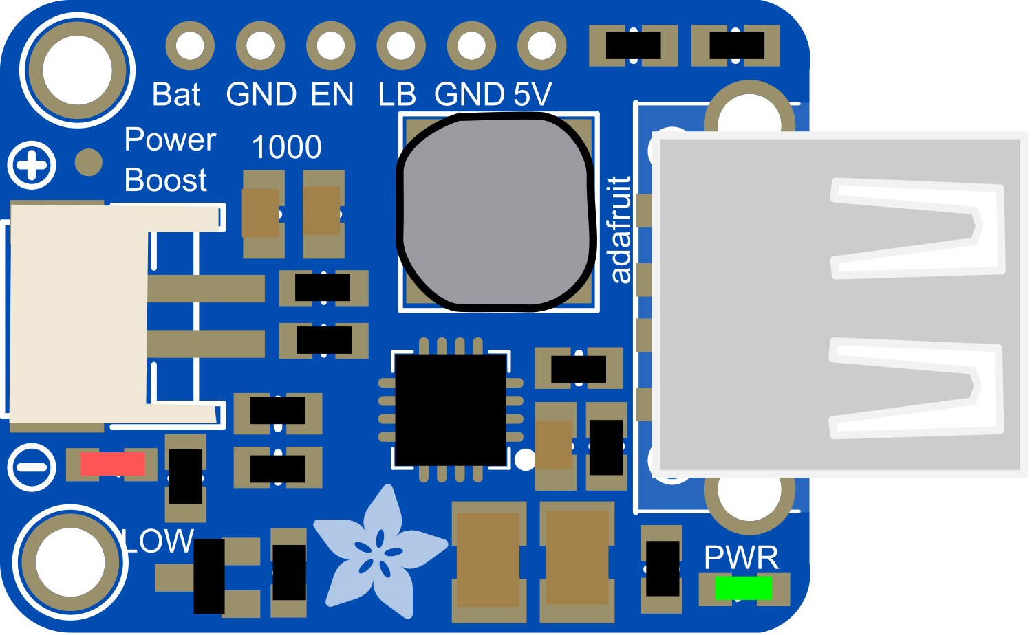
The PowerBoost 1000 Basic JST USB is a versatile and compact electronic component designed to provide a 5V power supply from a lower voltage source. This module is particularly useful for portable electronics, as it can boost the voltage from a battery to the level required by USB-powered devices. It is commonly used in DIY projects, wearables, and any application where a stable 5V output is needed from a rechargeable battery source.

Explore Projects Built with PowerBoost 1000 Basic JST USB

Use Cirkit Designer to design, explore, and prototype these projects online. Some projects support real-time simulation. Click "Open Project" to start designing instantly!
Battery-Powered Piezo Sensor Array with PowerBoost and Bridge Rectifier
Image of Copy of PIEZOELECTRIC : A project utilizing PowerBoost 1000 Basic JST USB in a practical application
This circuit uses multiple piezo sensors connected to bridge rectifiers to convert AC signals from the sensors into DC. The rectified DC is then used to charge a 18650 Li-ion battery, which powers a PowerBoost 1000 Basic module to provide a stable 5V output.
Cirkit Designer LogoOpen Project in Cirkit Designer
Battery-Powered Boost Converter with USB Type-C and BMS
Image of Weird Case: A project utilizing PowerBoost 1000 Basic JST USB in a practical application
This circuit is a power management and conversion system that includes a boost converter, battery management system (BMS), and various MOSFETs and passive components. It is designed to regulate and boost the voltage from a 2000mAh battery, providing stable power output through a USB Type C interface. The circuit also includes protection and switching mechanisms to ensure safe and efficient power delivery.
Cirkit Designer LogoOpen Project in Cirkit Designer
Arduino Mega 2560 Based Security System with Fingerprint Authentication and SMS Alerts
Image of Door security system: A project utilizing PowerBoost 1000 Basic JST USB in a practical application
This circuit features an Arduino Mega 2560 microcontroller interfaced with a SIM800L GSM module, two fingerprint scanners, an I2C LCD display, an IR sensor, and a piezo buzzer. Power management is handled by a PowerBoost 1000 Basic Pad USB, a TP4056 charging module, and a Li-ion 18650 battery, with an option to use a Mini AC-DC 110V-230V to 5V 700mA module for direct power supply. The primary functionality appears to be a security system with GSM communication capabilities, biometric access control, and visual/audible feedback.
Cirkit Designer LogoOpen Project in Cirkit Designer
Battery-Powered Raspberry Pi Zero with OLED Display and EmStat Pico for Portable Data Acquisition
Image of RPI Zero Prototype: A project utilizing PowerBoost 1000 Basic JST USB in a practical application
This circuit is a portable system powered by a 3.7V LiPo battery, which is boosted to 5V using an Adafruit PowerBoost 1000C to power a Raspberry Pi Zero and an EmStat Pico. The Raspberry Pi Zero interfaces with an OLED display via I2C and a tactile switch for user input, while the EmStat Pico communicates with the Raspberry Pi over UART for data acquisition or control purposes.
Cirkit Designer LogoOpen Project in Cirkit Designer

Explore Projects Built with PowerBoost 1000 Basic JST USB

Use Cirkit Designer to design, explore, and prototype these projects online. Some projects support real-time simulation. Click "Open Project" to start designing instantly!
Image of Copy of PIEZOELECTRIC : A project utilizing PowerBoost 1000 Basic JST USB in a practical application
Battery-Powered Piezo Sensor Array with PowerBoost and Bridge Rectifier
This circuit uses multiple piezo sensors connected to bridge rectifiers to convert AC signals from the sensors into DC. The rectified DC is then used to charge a 18650 Li-ion battery, which powers a PowerBoost 1000 Basic module to provide a stable 5V output.
Cirkit Designer LogoOpen Project in Cirkit Designer
Image of Weird Case: A project utilizing PowerBoost 1000 Basic JST USB in a practical application
Battery-Powered Boost Converter with USB Type-C and BMS
This circuit is a power management and conversion system that includes a boost converter, battery management system (BMS), and various MOSFETs and passive components. It is designed to regulate and boost the voltage from a 2000mAh battery, providing stable power output through a USB Type C interface. The circuit also includes protection and switching mechanisms to ensure safe and efficient power delivery.
Cirkit Designer LogoOpen Project in Cirkit Designer
Image of Door security system: A project utilizing PowerBoost 1000 Basic JST USB in a practical application
Arduino Mega 2560 Based Security System with Fingerprint Authentication and SMS Alerts
This circuit features an Arduino Mega 2560 microcontroller interfaced with a SIM800L GSM module, two fingerprint scanners, an I2C LCD display, an IR sensor, and a piezo buzzer. Power management is handled by a PowerBoost 1000 Basic Pad USB, a TP4056 charging module, and a Li-ion 18650 battery, with an option to use a Mini AC-DC 110V-230V to 5V 700mA module for direct power supply. The primary functionality appears to be a security system with GSM communication capabilities, biometric access control, and visual/audible feedback.
Cirkit Designer LogoOpen Project in Cirkit Designer
Image of RPI Zero Prototype: A project utilizing PowerBoost 1000 Basic JST USB in a practical application
Battery-Powered Raspberry Pi Zero with OLED Display and EmStat Pico for Portable Data Acquisition
This circuit is a portable system powered by a 3.7V LiPo battery, which is boosted to 5V using an Adafruit PowerBoost 1000C to power a Raspberry Pi Zero and an EmStat Pico. The Raspberry Pi Zero interfaces with an OLED display via I2C and a tactile switch for user input, while the EmStat Pico communicates with the Raspberry Pi over UART for data acquisition or control purposes.
Cirkit Designer LogoOpen Project in Cirkit Designer

Common Applications and Use Cases

  • Portable USB chargers
  • Battery-powered electronics
  • DIY USB power supplies
  • Wearable devices
  • Raspberry Pi and Arduino projects

Technical Specifications

Key Technical Details

  • Input Voltage: 1.8V to 5.5V
  • Output Voltage: 5V fixed
  • Output Current: Up to 1A
  • Efficiency: 90% typical at full load
  • Quiescent Current: <5mA
  • Switching Frequency: 1.2MHz

Pin Configuration and Descriptions

Pin Name Description
VIN Input voltage (1.8V to 5.5V)
GND Ground connection
5V Regulated output voltage (5V)
EN Enable pin (pull low to disable)
BAT Battery connection via JST connector

Usage Instructions

How to Use the Component in a Circuit

  1. Connecting the Battery:

    • Connect your battery to the JST connector labeled 'BAT'. Ensure correct polarity.
  2. Enabling the PowerBoost:

    • The 'EN' pin can be left unconnected for normal operation. To disable the PowerBoost, connect 'EN' to ground.
  3. Drawing Power:

    • Connect your USB device or other electronics to the '5V' and 'GND' pins for power.

Important Considerations and Best Practices

  • Battery Selection: Choose a battery that can supply the necessary current for your application.
  • Heat Dissipation: Ensure adequate ventilation around the component, as it may generate heat during operation.
  • Input Voltage: Do not exceed the recommended input voltage range to prevent damage.
  • Output Load: Avoid drawing more than 1A from the output to maintain stable operation.

Troubleshooting and FAQs

Common Issues

  • Insufficient Output Power: Ensure the input battery is fully charged and capable of delivering the required current.
  • Overheating: If the module is overheating, reduce the load or improve heat dissipation.
  • No Output Voltage: Check connections and ensure the 'EN' pin is not inadvertently grounded.

Solutions and Tips for Troubleshooting

  • Check Connections: Verify all connections are secure and correctly polarized.
  • Battery Charge: Ensure the battery is charged and functioning properly.
  • Load Testing: Test the output with a different load to rule out issues with the connected device.

FAQs

Q: Can I use the PowerBoost 1000 Basic with a solar panel? A: Yes, as long as the solar panel's output voltage is within the 1.8V to 5.5V range.

Q: Is it possible to charge the battery through the PowerBoost 1000 Basic? A: No, this module does not include a charging circuit. It is designed to boost voltage only.

Q: What type of battery connector is used? A: A standard 2-pin JST-PH connector is used for battery connection.

Q: Can I connect multiple devices to the PowerBoost 1000 Basic? A: Yes, but ensure the total current draw does not exceed 1A.

Example Arduino Connection (Optional)

If you're using the PowerBoost 1000 Basic with an Arduino UNO to power it from a battery, here's a simple connection guide:

  1. Connect the battery to the JST connector on the PowerBoost.
  2. Connect the '5V' pin of the PowerBoost to the '5V' pin on the Arduino UNO.
  3. Connect the 'GND' pin of the PowerBoost to one of the 'GND' pins on the Arduino UNO.
// No specific code is required for the PowerBoost 1000 Basic as it is a power supply component.
// However, ensure your Arduino sketch does not draw more than 1A from the 5V pin.

Remember, the PowerBoost 1000 Basic is a power supply component and does not require code for operation. The above connection allows you to power your Arduino project from a battery through the PowerBoost.