How to Use Raspberry Pi Zero 2W: Examples, Pinouts, and Specs
Introduction
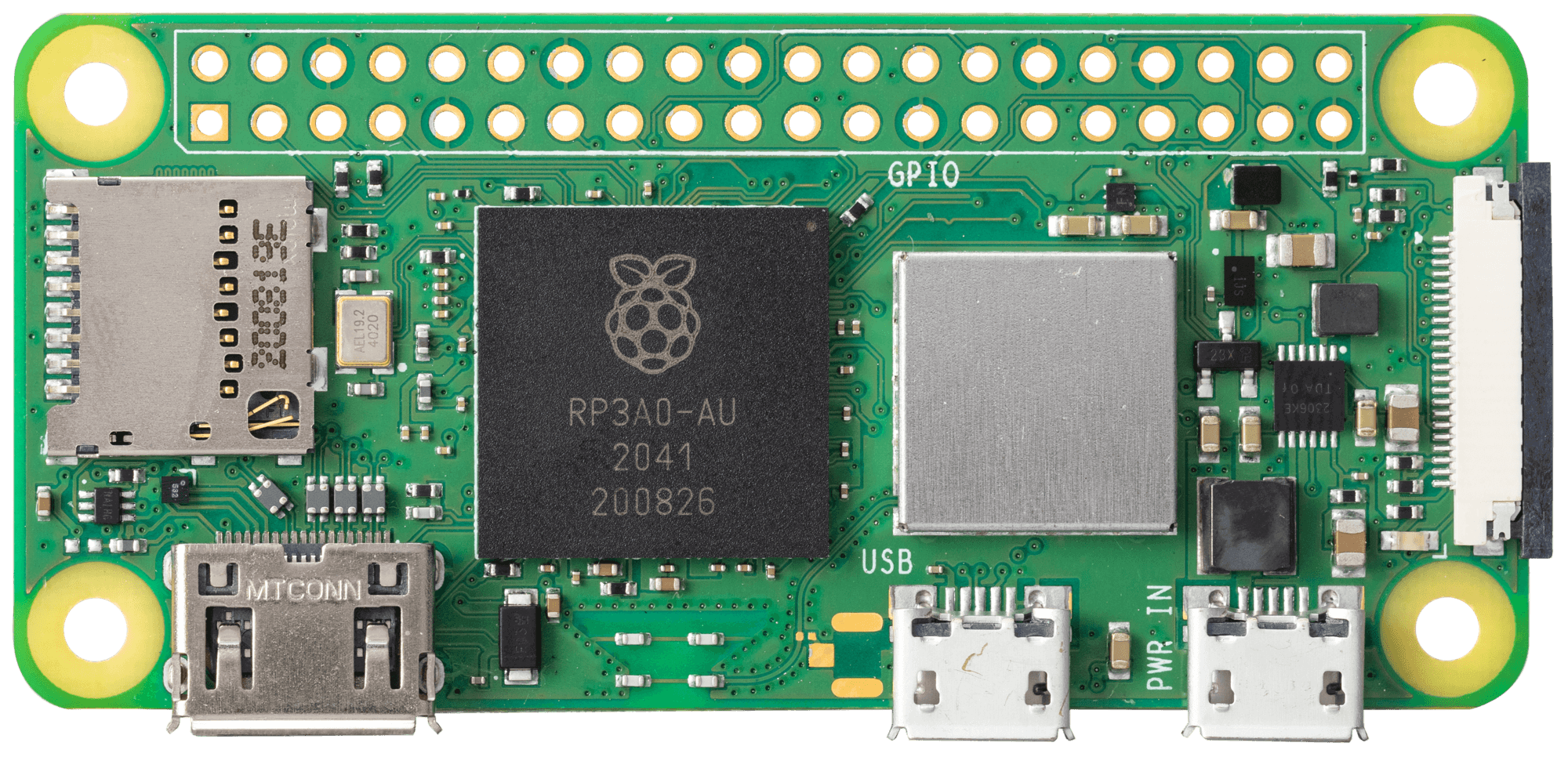
The Raspberry Pi Zero 2W, manufactured by Raspberry Pi, is a compact and affordable single-board computer designed for a wide range of applications. It features a quad-core processor, wireless connectivity, and GPIO pins, making it a versatile choice for DIY electronics projects, IoT devices, and embedded systems. Despite its small size, the Raspberry Pi Zero 2W delivers impressive performance and functionality, making it a popular choice among hobbyists and professionals alike.
Explore Projects Built with Raspberry Pi Zero 2W
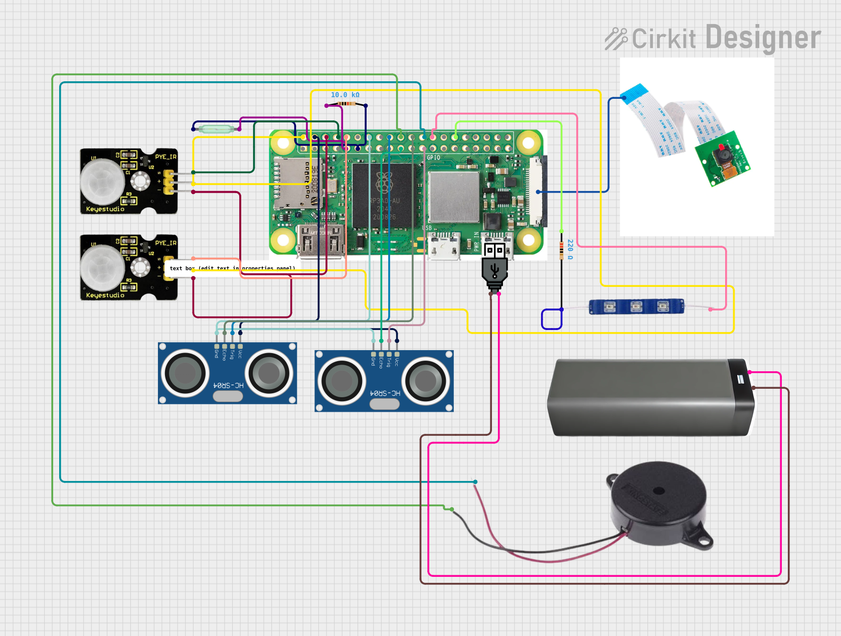
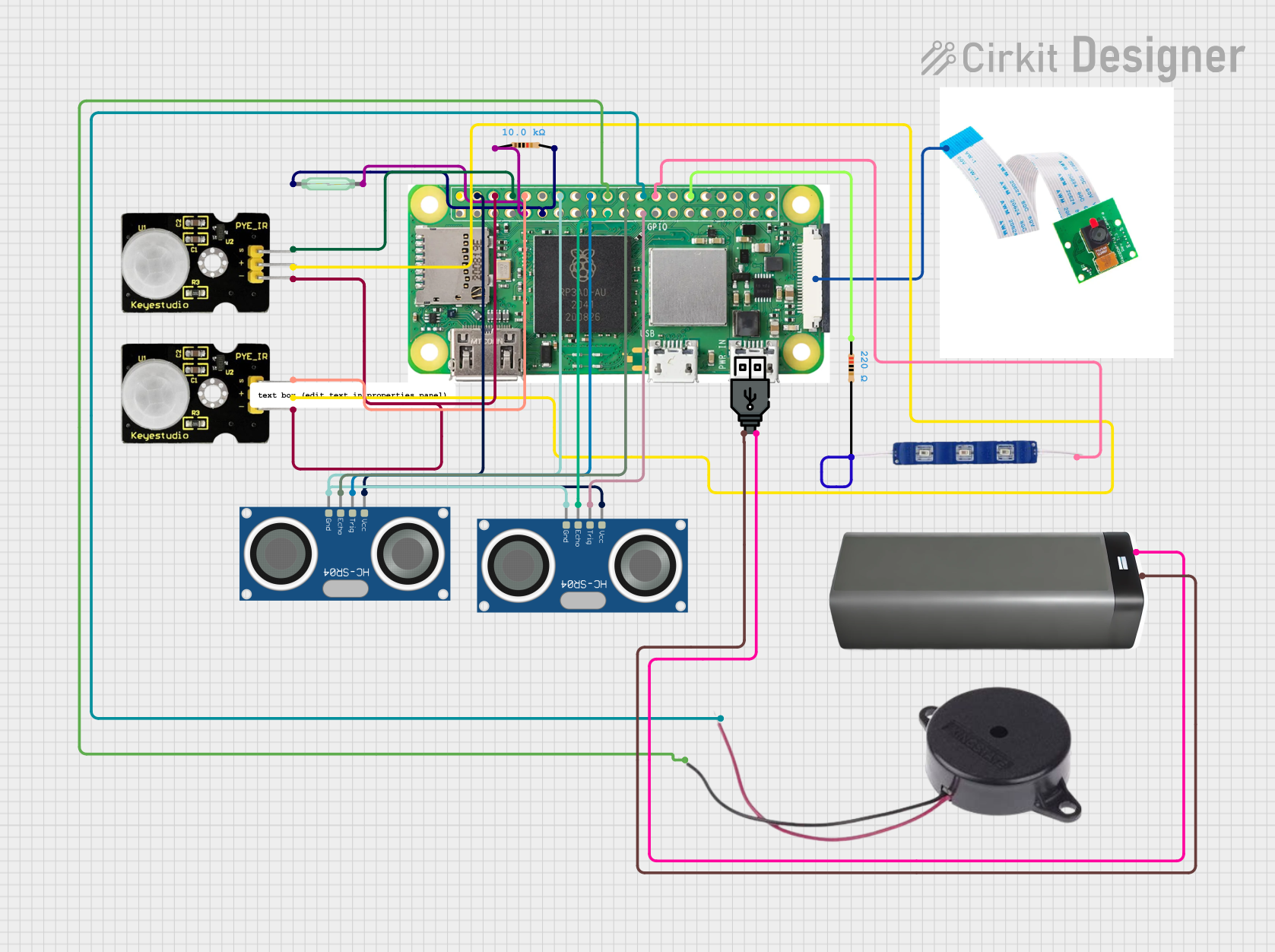
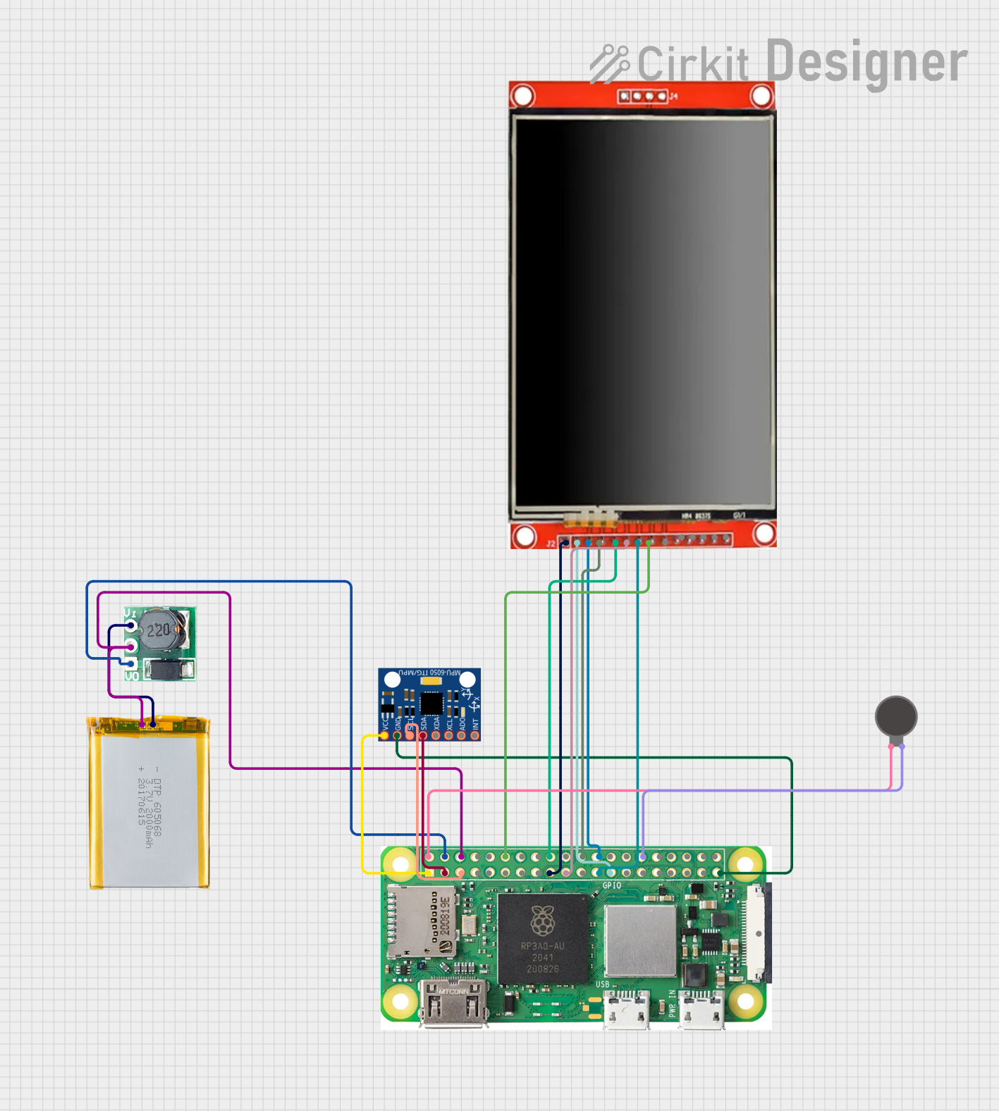

Explore Projects Built with Raspberry Pi Zero 2W
Common Applications and Use Cases
- IoT (Internet of Things) devices and smart home automation
- Robotics and control systems
- Media streaming and playback
- Portable gaming consoles
- Prototyping and educational projects
- Networked sensors and data logging
Technical Specifications
The Raspberry Pi Zero 2W is packed with features that make it a powerful yet compact computing platform. Below are its key technical specifications:
Key Technical Details
- Processor: Broadcom BCM2710A1, quad-core Cortex-A53, 64-bit, 1 GHz
- RAM: 512 MB LPDDR2
- Wireless Connectivity:
- 802.11 b/g/n Wi-Fi (2.4 GHz)
- Bluetooth 4.2, BLE
- GPIO: 40-pin header (unpopulated)
- Ports:
- Mini HDMI (video output, up to 1080p)
- Micro USB (data and power)
- MicroSD card slot (for storage and OS)
- Power Supply: 5V, 2.5A via micro USB
- Dimensions: 65mm × 30mm × 5mm
- Weight: Approximately 9g
Pin Configuration and Descriptions
The Raspberry Pi Zero 2W features a 40-pin GPIO header, which is unpopulated by default. Below is the pinout for the GPIO header:
| Pin Number | Pin Name | Functionality |
|---|---|---|
| 1 | 3.3V Power | 3.3V power supply |
| 2 | 5V Power | 5V power supply |
| 3 | GPIO2 (SDA1) | I2C Data |
| 4 | 5V Power | 5V power supply |
| 5 | GPIO3 (SCL1) | I2C Clock |
| 6 | Ground | Ground |
| 7 | GPIO4 | General-purpose I/O |
| 8 | GPIO14 (TXD) | UART Transmit |
| 9 | Ground | Ground |
| 10 | GPIO15 (RXD) | UART Receive |
| ... | ... | ... (Refer to full GPIO pinout) |
For the complete GPIO pinout, refer to the official Raspberry Pi documentation.
Usage Instructions
How to Use the Raspberry Pi Zero 2W in a Circuit
Prepare the Operating System:
- Download the Raspberry Pi OS from the official website.
- Flash the OS image onto a microSD card using tools like Balena Etcher.
- Insert the microSD card into the Raspberry Pi Zero 2W.
Power the Device:
- Connect a 5V, 2.5A power supply to the micro USB power port.
Connect Peripherals:
- Use a mini HDMI adapter to connect a display.
- Connect a USB OTG adapter for peripherals like a keyboard or mouse.
- Optionally, solder the GPIO header for interfacing with external components.
Access the Device:
- Use SSH to remotely access the Raspberry Pi if Wi-Fi is configured.
- Alternatively, connect a monitor and keyboard for direct access.
Important Considerations and Best Practices
- Ensure the power supply provides sufficient current (at least 2.5A) to avoid instability.
- Use a high-quality microSD card (Class 10 or higher) for better performance.
- Avoid shorting GPIO pins, as this can damage the board.
- Use proper heat management if running resource-intensive applications.
Example: Blinking an LED with GPIO
The following example demonstrates how to blink an LED using the GPIO pins of the Raspberry Pi Zero 2W. This example assumes the GPIO header is soldered and an LED is connected to GPIO17 (pin 11) with a resistor.
Circuit Setup
- Connect the longer leg (anode) of the LED to GPIO17 (pin 11).
- Connect the shorter leg (cathode) of the LED to a 330-ohm resistor.
- Connect the other end of the resistor to a ground pin (e.g., pin 6).
Python Code
Import the GPIO library and time module
import RPi.GPIO as GPIO import time
Set up GPIO mode and pin
GPIO.setmode(GPIO.BCM) # Use Broadcom pin numbering GPIO.setup(17, GPIO.OUT) # Set GPIO17 as an output pin
try: while True: GPIO.output(17, GPIO.HIGH) # Turn on the LED time.sleep(1) # Wait for 1 second GPIO.output(17, GPIO.LOW) # Turn off the LED time.sleep(1) # Wait for 1 second except KeyboardInterrupt: # Clean up GPIO settings on exit GPIO.cleanup()
Troubleshooting and FAQs
Common Issues and Solutions
The Raspberry Pi Zero 2W does not boot:
- Ensure the microSD card is properly inserted and contains a valid OS image.
- Verify the power supply provides at least 2.5A.
Wi-Fi connectivity issues:
- Check the Wi-Fi credentials in the
wpa_supplicant.conffile. - Ensure the device is within range of the Wi-Fi router.
- Check the Wi-Fi credentials in the
GPIO pins not working:
- Verify the GPIO pin numbering (BCM vs. physical pin numbers).
- Check for loose connections or soldering issues.
Overheating:
- Use a heatsink or active cooling if running resource-intensive tasks.
FAQs
Can I use the Raspberry Pi Zero 2W for AI/ML projects?
- Yes, lightweight AI/ML models can run on the Raspberry Pi Zero 2W, but for more demanding tasks, consider using a Raspberry Pi 4.
Does the Raspberry Pi Zero 2W support USB boot?
- No, the Raspberry Pi Zero 2W boots exclusively from a microSD card.
Can I power the Raspberry Pi Zero 2W via GPIO pins?
- Yes, you can supply 5V to the 5V GPIO pin, but ensure proper voltage regulation.
This concludes the documentation for the Raspberry Pi Zero 2W. For further details, refer to the official Raspberry Pi website.