How to Use M12-5P-Male: Examples, Pinouts, and Specs
Introduction
The M12-5P-Male is a 5-pin male connector widely used in industrial applications for connecting sensors, actuators, and other devices. Its circular design ensures secure and reliable connections, even in harsh environments. This connector is known for its durability, resistance to vibration, and ability to maintain stable electrical connections under challenging conditions.
Explore Projects Built with M12-5P-Male


Explore Projects Built with M12-5P-Male
Common Applications and Use Cases
- Industrial automation systems
- Robotics and machinery
- Sensor and actuator connections
- Process control and monitoring
- Outdoor and rugged environments requiring IP-rated connectors
Technical Specifications
The M12-5P-Male connector is designed to meet industrial standards, ensuring compatibility and reliability in demanding applications. Below are its key technical details:
General Specifications
| Parameter | Value |
|---|---|
| Connector Type | M12 Circular Male Connector |
| Number of Pins | 5 |
| Rated Voltage | 60V AC/DC |
| Rated Current | 4A per pin |
| Contact Resistance | ≤ 5 mΩ |
| Insulation Resistance | ≥ 100 MΩ |
| Operating Temperature | -25°C to +85°C |
| IP Rating | IP67 (when mated) |
| Housing Material | Nickel-plated brass or plastic |
| Contact Material | Gold-plated brass |
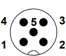
Pin Configuration and Descriptions
The M12-5P-Male connector features five pins arranged in a circular pattern. Below is the pinout and description:
| Pin Number | Signal/Function | Description |
|---|---|---|
| 1 | V+ | Positive supply voltage |
| 2 | Signal 1 | Signal or data line 1 |
| 3 | V- | Ground or negative supply voltage |
| 4 | Signal 2 | Signal or data line 2 |
| 5 | Shield/PE (optional) | Protective earth or shielding |
Note: The exact pinout may vary depending on the application or device. Always refer to the manufacturer's datasheet for specific details.
Usage Instructions
The M12-5P-Male connector is straightforward to use but requires proper handling to ensure reliable performance. Follow these steps and best practices:
How to Use the Connector in a Circuit
- Identify the Pinout: Refer to the pin configuration table above to identify the correct pins for your application.
- Prepare the Cable: Strip the cable insulation to expose the wires. Ensure the wires are clean and free of damage.
- Solder or Crimp the Wires: Depending on the connector type, solder or crimp the wires to the corresponding pins.
- Assemble the Connector: If the connector is a field-attachable type, assemble the housing securely after connecting the wires.
- Connect to the Device: Align the connector with the mating port and screw it in place to ensure a secure connection.
Important Considerations and Best Practices
- Ensure Proper Alignment: Always align the connector properly before mating to avoid damaging the pins.
- Use IP67-Rated Components: For outdoor or harsh environments, ensure the connector is mated with an IP67-rated counterpart.
- Avoid Over-Tightening: Tighten the connector firmly but avoid over-tightening, which may damage the threads.
- Inspect Regularly: Periodically inspect the connector for wear, corrosion, or damage, especially in demanding environments.
Example: Connecting to an Arduino UNO
The M12-5P-Male connector can be used to interface sensors or actuators with an Arduino UNO. Below is an example of connecting a sensor with a 5-pin M12 connector to an Arduino:
Wiring Diagram
| M12 Pin | Arduino Pin | Description |
|---|---|---|
| 1 (V+) | 5V | Power supply to the sensor |
| 2 (Signal 1) | A0 | Sensor output to analog pin |
| 3 (V-) | GND | Ground connection |
| 4 (Signal 2) | D2 | Digital signal input/output |
| 5 (Shield) | GND | Shielding (optional) |
Arduino Code Example
// Example code for reading an analog sensor connected via M12-5P-Male connector
const int sensorPin = A0; // Pin connected to Signal 1 (analog output)
int sensorValue = 0;      // Variable to store sensor reading

void setup() {
  Serial.begin(9600); // Initialize serial communication
  pinMode(sensorPin, INPUT); // Set sensor pin as input
}

void loop() {
  sensorValue = analogRead(sensorPin); // Read the sensor value
  Serial.print("Sensor Value: ");
  Serial.println(sensorValue); // Print the sensor value to the Serial Monitor
  delay(500); // Wait for 500ms before the next reading
}
Troubleshooting and FAQs
Common Issues and Solutions
Loose Connection:
- Issue: The connector is not securely mated, causing intermittent signals.
- Solution: Ensure the connector is properly aligned and tightened.
Corrosion or Damage:
- Issue: The connector pins or housing show signs of corrosion or physical damage.
- Solution: Replace the connector and ensure proper sealing for outdoor use.
Incorrect Pinout:
- Issue: The device does not function as expected due to incorrect wiring.
- Solution: Double-check the pinout and wiring connections against the datasheet.
Signal Interference:
- Issue: Noise or interference affects the signal quality.
- Solution: Use shielded cables and connect the shield to the ground (Pin 5).
FAQs
Q1: Can the M12-5P-Male connector handle high currents?
A1: No, the connector is rated for a maximum current of 4A per pin. For higher currents, consider using a different connector.
Q2: Is the connector waterproof?
A2: Yes, the M12-5P-Male connector is IP67-rated when mated, making it suitable for wet or dusty environments.
Q3: Can I use this connector for high-speed data transmission?
A3: Yes, the M12-5P-Male connector can support high-speed data transmission, but ensure the cable and device are compatible.
Q4: How do I clean the connector?
A4: Use a soft brush or compressed air to remove debris. Avoid using harsh chemicals that may damage the contacts.
By following this documentation, you can effectively use the M12-5P-Male connector in your projects and ensure reliable performance in industrial applications.