Cirkit Designer Logo
Cirkit Designer
Your all-in-one circuit design IDE
Home / 
Component Documentation

How to Use Adafruit Feather M4 Express CAN: Examples, Pinouts, and Specs

Image of Adafruit Feather M4 Express CAN
Cirkit Designer LogoDesign with Adafruit Feather M4 Express CAN in Cirkit Designer

Introduction

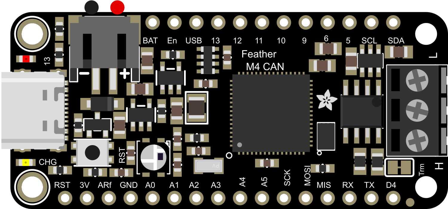
The Adafruit Feather M4 Express CAN is a versatile and powerful development board that harnesses the capabilities of the ATSAMD51 microcontroller. This board is part of the Feather ecosystem, known for its compact size, portability, and extensive I/O options. The inclusion of CAN-Bus connectivity makes it ideal for automotive applications, industrial automation, and any project where robust serial communication is required. The ARM Cortex-M4 core with a floating-point unit runs at 120 MHz, providing high computational performance for complex tasks.

Explore Projects Built with Adafruit Feather M4 Express CAN

Use Cirkit Designer to design, explore, and prototype these projects online. Some projects support real-time simulation. Click "Open Project" to start designing instantly!
Touch-Sensitive Interface with Adafruit MPR121 and Feather 32u4 Bluefruit
Image of MPR121: A project utilizing Adafruit Feather M4 Express CAN in a practical application
This circuit integrates an Adafruit MPR121 capacitive touch sensor with an Adafruit Feather 32u4 Bluefruit microcontroller. The MPR121 is powered by the Feather and communicates via I2C (SCL and SDA) to detect touch inputs, which can be processed or transmitted wirelessly by the Feather.
Cirkit Designer LogoOpen Project in Cirkit Designer
Adafruit Feather 32u4 Bluefruit with MPR121 Capacitive Touch Sensor Interface
Image of ALi WTSE: A project utilizing Adafruit Feather M4 Express CAN in a practical application
This circuit integrates an Adafruit MPR121 capacitive touch sensor with an Adafruit Feather 32u4 Bluefruit microcontroller. The MPR121 is powered by the 3.3V supply from the Feather and communicates with the microcontroller via I2C, with SCL connected to pin 3 and SDA connected to pin 2 of the Feather. This setup allows the Feather to detect touch inputs from the MPR121 for further processing or wireless communication.
Cirkit Designer LogoOpen Project in Cirkit Designer
Solar-Powered Environmental Data Logger with Adafruit Feather M0 Express
Image of Lake Thoreau Monitoring Station: A project utilizing Adafruit Feather M4 Express CAN in a practical application
This circuit is designed for environmental data collection and logging, utilizing an Adafruit Feather M0 Express microcontroller as the central processing unit. It interfaces with a BME280 sensor for atmospheric temperature, humidity, and pressure measurements, an SGP30 sensor for monitoring air quality (eCO2 and TVOC), and a STEMMA soil sensor for detecting soil moisture and temperature. The system is powered by a solar panel and a 3.7v LiPo battery, managed by an Adafruit BQ24074 Solar-DC-USB Lipo Charger, and provides easy access to the microcontroller's connections through an Adafruit Terminal Breakout FeatherWing.
Cirkit Designer LogoOpen Project in Cirkit Designer
ESP32-S3 GPS Logger and Wind Speed Display with Dual OLED and CAN Bus
Image of Copy of esp32-s3-ellipse: A project utilizing Adafruit Feather M4 Express CAN in a practical application
This circuit features an ESP32-S3 microcontroller interfaced with an SD card, two OLED displays, a GPS module, and a CAN bus module. It records GPS data to the SD card every second, displays speed in knots on one OLED display, and shows wind speed from the CAN bus in NMEA 2000 format on the other OLED display.
Cirkit Designer LogoOpen Project in Cirkit Designer

Explore Projects Built with Adafruit Feather M4 Express CAN

Use Cirkit Designer to design, explore, and prototype these projects online. Some projects support real-time simulation. Click "Open Project" to start designing instantly!
Image of MPR121: A project utilizing Adafruit Feather M4 Express CAN in a practical application
Touch-Sensitive Interface with Adafruit MPR121 and Feather 32u4 Bluefruit
This circuit integrates an Adafruit MPR121 capacitive touch sensor with an Adafruit Feather 32u4 Bluefruit microcontroller. The MPR121 is powered by the Feather and communicates via I2C (SCL and SDA) to detect touch inputs, which can be processed or transmitted wirelessly by the Feather.
Cirkit Designer LogoOpen Project in Cirkit Designer
Image of ALi WTSE: A project utilizing Adafruit Feather M4 Express CAN in a practical application
Adafruit Feather 32u4 Bluefruit with MPR121 Capacitive Touch Sensor Interface
This circuit integrates an Adafruit MPR121 capacitive touch sensor with an Adafruit Feather 32u4 Bluefruit microcontroller. The MPR121 is powered by the 3.3V supply from the Feather and communicates with the microcontroller via I2C, with SCL connected to pin 3 and SDA connected to pin 2 of the Feather. This setup allows the Feather to detect touch inputs from the MPR121 for further processing or wireless communication.
Cirkit Designer LogoOpen Project in Cirkit Designer
Image of Lake Thoreau Monitoring Station: A project utilizing Adafruit Feather M4 Express CAN in a practical application
Solar-Powered Environmental Data Logger with Adafruit Feather M0 Express
This circuit is designed for environmental data collection and logging, utilizing an Adafruit Feather M0 Express microcontroller as the central processing unit. It interfaces with a BME280 sensor for atmospheric temperature, humidity, and pressure measurements, an SGP30 sensor for monitoring air quality (eCO2 and TVOC), and a STEMMA soil sensor for detecting soil moisture and temperature. The system is powered by a solar panel and a 3.7v LiPo battery, managed by an Adafruit BQ24074 Solar-DC-USB Lipo Charger, and provides easy access to the microcontroller's connections through an Adafruit Terminal Breakout FeatherWing.
Cirkit Designer LogoOpen Project in Cirkit Designer
Image of Copy of esp32-s3-ellipse: A project utilizing Adafruit Feather M4 Express CAN in a practical application
ESP32-S3 GPS Logger and Wind Speed Display with Dual OLED and CAN Bus
This circuit features an ESP32-S3 microcontroller interfaced with an SD card, two OLED displays, a GPS module, and a CAN bus module. It records GPS data to the SD card every second, displays speed in knots on one OLED display, and shows wind speed from the CAN bus in NMEA 2000 format on the other OLED display.
Cirkit Designer LogoOpen Project in Cirkit Designer

Common Applications and Use Cases

  • Automotive diagnostics and networking
  • Industrial control systems
  • Home automation
  • Robotics
  • Data logging and telemetry

Technical Specifications

Key Technical Details

  • Microcontroller: ATSAMD51J19
  • Clock Speed: 120 MHz
  • Flash Memory: 512 KB
  • SRAM: 192 KB
  • Operating Voltage: 3.3V
  • I/O Pins: 21, with 12 PWM and 6 ADC channels
  • CAN Controller: MCP2515 with SN65HVD230 transceiver

Pin Configuration and Descriptions

Pin Number Function Description
1 GND Ground
2 3V 3.3V power supply output
3 AREF Analog reference voltage for ADC
4-9 A0-A5 Analog input pins
10-15 D5-D10 Digital I/O pins, PWM capable
16-17 SCK, MISO, MOSI SPI communication pins
18-19 SDA, SCL I2C communication pins
20 RX UART receive pin
21 TX UART transmit pin
22 CAN_RX CAN-Bus receive pin
23 CAN_TX CAN-Bus transmit pin

Usage Instructions

How to Use the Component in a Circuit

  1. Powering the Board: Connect a 3.7V LiPo battery to the JST connector for portable applications or supply 5V to the USB or VBUS pin for stationary projects.
  2. Programming: Use the USB interface to program the board with the Arduino IDE or CircuitPython.
  3. Connecting to CAN-Bus: Attach the CAN_H and CAN_L lines from your CAN network to the CAN_RX and CAN_TX pins, respectively.

Important Considerations and Best Practices

  • Ensure that the power supply is within the recommended voltage range to prevent damage.
  • When using the CAN-Bus, a 120-ohm termination resistor may be necessary at both ends of the bus for proper communication.
  • Use proper ESD precautions when handling the board to avoid static damage to the microcontroller.

Troubleshooting and FAQs

Common Issues Users Might Face

  • Board not recognized by computer: Check the USB cable and connections; try a different USB port or cable.
  • CAN-Bus communication errors: Verify the termination resistors and the integrity of the CAN_H and CAN_L connections.
  • Sketch upload failure: Ensure the correct board and port are selected in the Arduino IDE.

Solutions and Tips for Troubleshooting

  • If the board is not recognized, press the reset button twice quickly to enter bootloader mode.
  • For CAN-Bus issues, use a CAN-Bus analyzer to monitor the network and diagnose communication problems.
  • Check for updates to board definitions or drivers if you encounter upload issues.

Example Code for Arduino UNO

#include <SPI.h>
#include <mcp_can.h>

// Initialize MCP_CAN instance with SPI CS Pin 10
MCP_CAN CAN0(10);

void setup() {
  Serial.begin(115200);

  // Initialize CAN0 at 500 kbps
  if (CAN0.begin(MCP_ANY, CAN_500KBPS, MCP_8MHZ) == CAN_OK) {
    Serial.println("CAN Bus Module Initialized Successfully!");
  } else {
    Serial.println("CAN Bus Module Initialization Failed!");
  }
}

void loop() {
  // Check if data is available to read
  if (CAN0.checkReceive() == CAN_MSGAVAIL) {
    unsigned char len = 0;
    unsigned char buf[8];

    // Read data: len = data length, buf = data byte(s)
    CAN0.readMsgBuf(&len, buf);

    // Print received data
    for (int i = 0; i < len; i++) {
      Serial.print(buf[i], HEX);
      Serial.print(" ");
    }
    Serial.println();
  }
}

Note: This example demonstrates basic CAN-Bus communication using the MCP_CAN library. Ensure that the library is installed in your Arduino IDE before compiling the sketch. Adjust the CS pin number and CAN bus speed according to your specific setup.