Cirkit Designer Logo
Cirkit Designer
Your all-in-one circuit design IDE
Home / 
Component Documentation

How to Use Ai-Thinker GP-02 Precision GPS/GNSS Module: Examples, Pinouts, and Specs

Image of Ai-Thinker GP-02 Precision GPS/GNSS Module
Cirkit Designer LogoDesign with Ai-Thinker GP-02 Precision GPS/GNSS Module in Cirkit Designer

Introduction

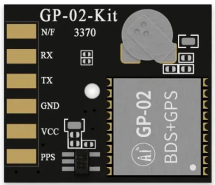
The Ai-Thinker GP-02 is a compact and high-performance GPS/GNSS module designed for precision positioning applications. Manufactured by Shenzhen Ai-Thinker Technology Co., Ltd., this module supports multiple satellite navigation systems, including GPS, GLONASS, and BeiDou, ensuring reliable and accurate location data. Its low power consumption and small form factor make it ideal for integration into portable devices, IoT applications, and automotive systems.

Explore Projects Built with Ai-Thinker GP-02 Precision GPS/GNSS Module

Use Cirkit Designer to design, explore, and prototype these projects online. Some projects support real-time simulation. Click "Open Project" to start designing instantly!
Solar-Powered GSM/GPRS+GPS Tracker with Seeeduino XIAO
Image of SOS System : A project utilizing Ai-Thinker GP-02 Precision GPS/GNSS Module in a practical application
This circuit features an Ai Thinker A9G development board for GSM/GPRS and GPS/BDS connectivity, interfaced with a Seeeduino XIAO microcontroller for control and data processing. A solar cell, coupled with a TP4056 charging module, charges a 3.3V battery, which powers the system through a 3.3V regulator ensuring stable operation. The circuit likely serves for remote data communication and location tracking, with the capability to be powered by renewable energy and interfaced with additional sensors or input devices via the Seeeduino XIAO.
Cirkit Designer LogoOpen Project in Cirkit Designer
Arduino UNO with A9G GSM/GPRS and Dual VL53L1X Distance Sensors
Image of TED CIRCUIT : A project utilizing Ai-Thinker GP-02 Precision GPS/GNSS Module in a practical application
This circuit features an Arduino UNO microcontroller interfaced with an A9G GSM/GPRS+GPS/BDS module and two VL53L1X time-of-flight distance sensors. The A9G module is connected to the Arduino via serial communication for GPS and GSM functionalities, while both VL53L1X sensors are connected through I2C with shared SDA and SCL lines and individual SHUT pins for selective sensor activation. The Arduino is programmed to control these peripherals, although the specific functionality is not detailed in the provided code.
Cirkit Designer LogoOpen Project in Cirkit Designer
Arduino Nano Based GPS Tracker with GSM Communication and Accelerometer
Image of Circuit Aayush: A project utilizing Ai-Thinker GP-02 Precision GPS/GNSS Module in a practical application
This circuit is designed for communication and location tracking purposes. It features an Arduino Nano interfaced with a SIM800L GSM module for cellular connectivity, a GPS NEO 6M module for obtaining geographical coordinates, and an AITrip ADXL335 GY-61 accelerometer for motion sensing. The LM2596 Step Down Module is used to regulate the power supply to the components.
Cirkit Designer LogoOpen Project in Cirkit Designer
Raspberry Pi Pico-Based Navigation Assistant with Bluetooth and GPS
Image of sat_dish: compass example: A project utilizing Ai-Thinker GP-02 Precision GPS/GNSS Module in a practical application
This circuit features a Raspberry Pi Pico microcontroller interfaced with an HC-05 Bluetooth module for wireless communication, an HMC5883L compass module for magnetic field measurement, and a GPS NEO 6M module for location tracking. The Pico is configured to communicate with the HC-05 via serial connection (TX/RX), with the compass module via I2C (SCL/SDA), and with the GPS module via serial (TX/RX). Common power (VCC) and ground (GND) lines are shared among all modules, indicating a unified power system.
Cirkit Designer LogoOpen Project in Cirkit Designer

Explore Projects Built with Ai-Thinker GP-02 Precision GPS/GNSS Module

Use Cirkit Designer to design, explore, and prototype these projects online. Some projects support real-time simulation. Click "Open Project" to start designing instantly!
Image of SOS System : A project utilizing Ai-Thinker GP-02 Precision GPS/GNSS Module in a practical application
Solar-Powered GSM/GPRS+GPS Tracker with Seeeduino XIAO
This circuit features an Ai Thinker A9G development board for GSM/GPRS and GPS/BDS connectivity, interfaced with a Seeeduino XIAO microcontroller for control and data processing. A solar cell, coupled with a TP4056 charging module, charges a 3.3V battery, which powers the system through a 3.3V regulator ensuring stable operation. The circuit likely serves for remote data communication and location tracking, with the capability to be powered by renewable energy and interfaced with additional sensors or input devices via the Seeeduino XIAO.
Cirkit Designer LogoOpen Project in Cirkit Designer
Image of TED CIRCUIT : A project utilizing Ai-Thinker GP-02 Precision GPS/GNSS Module in a practical application
Arduino UNO with A9G GSM/GPRS and Dual VL53L1X Distance Sensors
This circuit features an Arduino UNO microcontroller interfaced with an A9G GSM/GPRS+GPS/BDS module and two VL53L1X time-of-flight distance sensors. The A9G module is connected to the Arduino via serial communication for GPS and GSM functionalities, while both VL53L1X sensors are connected through I2C with shared SDA and SCL lines and individual SHUT pins for selective sensor activation. The Arduino is programmed to control these peripherals, although the specific functionality is not detailed in the provided code.
Cirkit Designer LogoOpen Project in Cirkit Designer
Image of Circuit Aayush: A project utilizing Ai-Thinker GP-02 Precision GPS/GNSS Module in a practical application
Arduino Nano Based GPS Tracker with GSM Communication and Accelerometer
This circuit is designed for communication and location tracking purposes. It features an Arduino Nano interfaced with a SIM800L GSM module for cellular connectivity, a GPS NEO 6M module for obtaining geographical coordinates, and an AITrip ADXL335 GY-61 accelerometer for motion sensing. The LM2596 Step Down Module is used to regulate the power supply to the components.
Cirkit Designer LogoOpen Project in Cirkit Designer
Image of sat_dish: compass example: A project utilizing Ai-Thinker GP-02 Precision GPS/GNSS Module in a practical application
Raspberry Pi Pico-Based Navigation Assistant with Bluetooth and GPS
This circuit features a Raspberry Pi Pico microcontroller interfaced with an HC-05 Bluetooth module for wireless communication, an HMC5883L compass module for magnetic field measurement, and a GPS NEO 6M module for location tracking. The Pico is configured to communicate with the HC-05 via serial connection (TX/RX), with the compass module via I2C (SCL/SDA), and with the GPS module via serial (TX/RX). Common power (VCC) and ground (GND) lines are shared among all modules, indicating a unified power system.
Cirkit Designer LogoOpen Project in Cirkit Designer

Common Applications and Use Cases

  • IoT Devices: Location tracking for smart devices and wearables.
  • Automotive Systems: Navigation and fleet management.
  • Drones and Robotics: High-precision positioning for autonomous systems.
  • Geolocation Services: Mapping, surveying, and outdoor navigation.
  • Asset Tracking: Monitoring the location of valuable goods and equipment.

Technical Specifications

Key Technical Details

Parameter Value
Manufacturer Ai-Thinker (Shenzhen Ai-Thinker Technology Co., Ltd.)
Part Number GP-02
Satellite Systems Supported GPS, GLONASS, BeiDou
Positioning Accuracy < 2.5 meters (CEP)
Cold Start Time < 35 seconds
Hot Start Time < 1 second
Operating Voltage 3.0V to 3.6V
Operating Current 25mA (typical)
Communication Interface UART (default baud rate: 9600 bps)
Operating Temperature -40°C to +85°C
Dimensions 16mm x 12mm x 2.4mm

Pin Configuration and Descriptions

The GP-02 module has a total of 8 pins. Below is the pinout and description:

Pin Number Pin Name Description
1 VCC Power supply input (3.0V to 3.6V)
2 GND Ground
3 TXD UART Transmit (data output)
4 RXD UART Receive (data input)
5 PPS Pulse Per Second (timing signal output)
6 EN Enable pin (active high)
7 NC Not connected
8 ANT External antenna connection

Usage Instructions

How to Use the GP-02 in a Circuit

  1. Power Supply: Connect the VCC pin to a regulated 3.3V power source and the GND pin to ground.
  2. UART Communication: Connect the TXD and RXD pins to the corresponding UART pins of your microcontroller or development board (e.g., Arduino UNO).
  3. Antenna: Attach an external active antenna to the ANT pin for optimal satellite signal reception.
  4. Enable Pin: Pull the EN pin high to activate the module. If unused, connect it to VCC.
  5. PPS Signal: Use the PPS pin for precise timing applications if required.

Important Considerations and Best Practices

  • Antenna Placement: Ensure the external antenna has a clear view of the sky for optimal satellite reception.
  • Power Supply: Use a stable and noise-free power source to avoid interference with the module's operation.
  • UART Configuration: The default baud rate is 9600 bps. Configure your microcontroller's UART settings accordingly.
  • Startup Time: Allow sufficient time for the module to acquire satellite signals, especially during a cold start.

Example: Connecting GP-02 to an Arduino UNO

Below is an example of how to interface the GP-02 module with an Arduino UNO and read GPS data:

Circuit Connections

GP-02 Pin Arduino UNO Pin
VCC 3.3V
GND GND
TXD Pin 10 (RX via SoftwareSerial)
RXD Pin 11 (TX via SoftwareSerial)
EN 3.3V
ANT External antenna

Arduino Code

#include <SoftwareSerial.h>

// Define SoftwareSerial pins for GP-02 communication
SoftwareSerial gpsSerial(10, 11); // RX = Pin 10, TX = Pin 11

void setup() {
  // Initialize serial communication
  Serial.begin(9600); // For debugging via Serial Monitor
  gpsSerial.begin(9600); // For communication with GP-02 module

  Serial.println("GP-02 GPS Module Test");
}

void loop() {
  // Check if data is available from the GPS module
  while (gpsSerial.available()) {
    char c = gpsSerial.read(); // Read one character from the GPS module
    Serial.print(c); // Print the character to the Serial Monitor
  }
}

Note: Ensure the Arduino UNO is powered via USB or an external power source when using the GP-02 module.


Troubleshooting and FAQs

Common Issues and Solutions

  1. No GPS Data Output:

    • Cause: Incorrect UART connections or baud rate mismatch.
    • Solution: Verify the TXD and RXD connections and ensure the baud rate is set to 9600 bps.
  2. Poor Satellite Signal:

    • Cause: Obstructed antenna placement or interference.
    • Solution: Place the antenna in an open area with a clear view of the sky. Avoid placing it near electronic devices that may cause interference.
  3. Module Not Powering On:

    • Cause: Insufficient or unstable power supply.
    • Solution: Ensure the VCC pin is supplied with a stable 3.3V and the GND pin is properly connected.
  4. PPS Signal Not Working:

    • Cause: PPS pin not connected or module not locked onto satellites.
    • Solution: Verify the PPS connection and ensure the module has acquired satellite signals.

FAQs

  • Q: Can the GP-02 module operate at 5V?
    A: No, the GP-02 module requires a power supply of 3.0V to 3.6V. Using 5V may damage the module.

  • Q: How many satellites does the GP-02 support simultaneously?
    A: The GP-02 can track up to 22 satellites simultaneously, depending on the satellite system and signal conditions.

  • Q: Is the GP-02 compatible with NMEA protocol?
    A: Yes, the GP-02 outputs data in standard NMEA format, which is widely supported by GPS software and libraries.

  • Q: Can I use the GP-02 indoors?
    A: While the GP-02 may work indoors, satellite signal reception is typically weaker. For best results, use the module outdoors or near a window.


This concludes the documentation for the Ai-Thinker GP-02 Precision GPS/GNSS Module.