How to Use Key Studo Buzzer: Examples, Pinouts, and Specs
Introduction
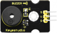
The Key Studo Buzzer is an electronic component designed to produce sound when an electrical signal is applied. It is widely used in various applications, including alarms, notifications, and electronic projects, to provide audible feedback. This component is simple to use and integrates seamlessly into circuits, making it ideal for both beginners and experienced electronics enthusiasts.
Explore Projects Built with Key Studo Buzzer
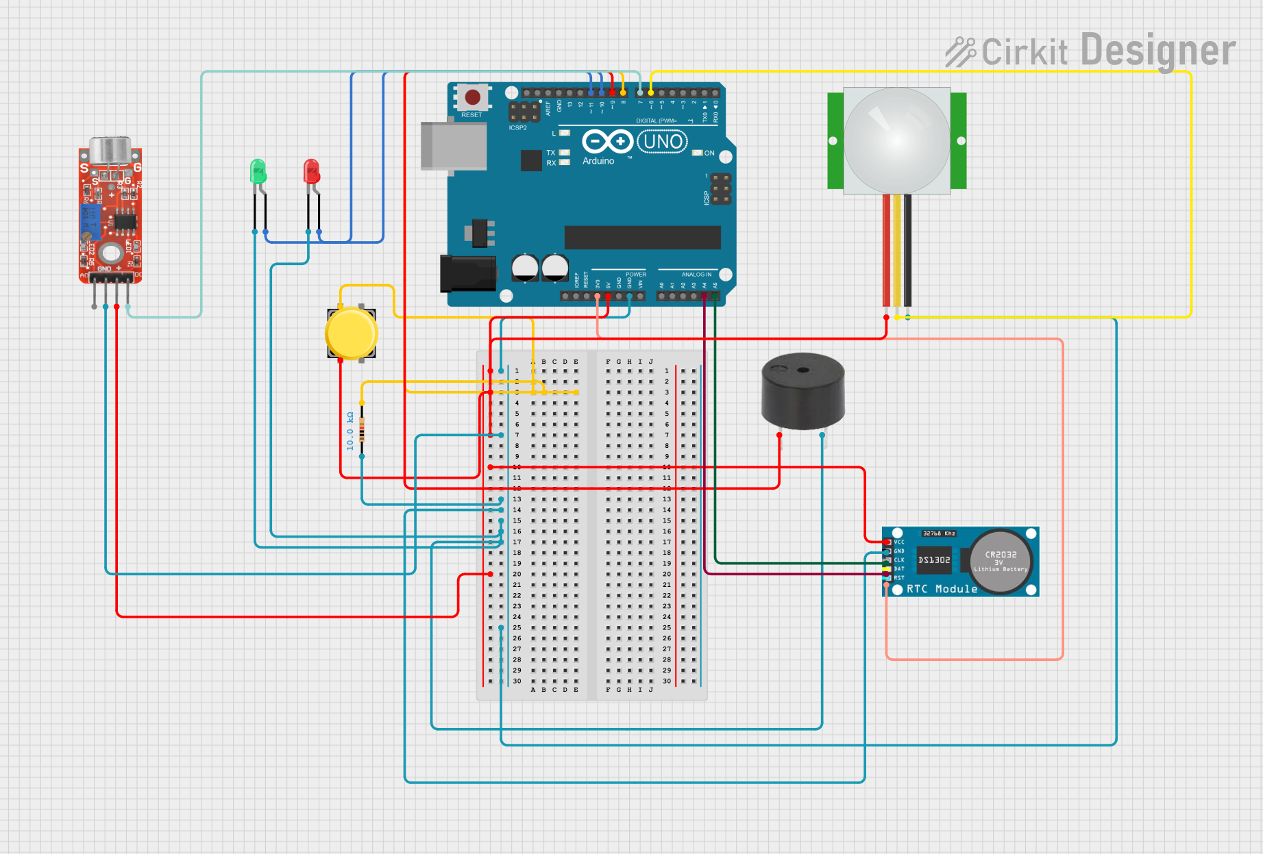


Explore Projects Built with Key Studo Buzzer
Common Applications and Use Cases
- Alarm systems for security or safety alerts
- Notification systems in devices or appliances
- Audible feedback in electronic projects
- Educational projects and prototyping with microcontrollers (e.g., Arduino)
Technical Specifications
The following table outlines the key technical details of the Key Studo Buzzer:
| Parameter | Specification |
|---|---|
| Operating Voltage | 3.3V to 5V |
| Operating Current | ≤ 20mA |
| Sound Frequency | ~2 kHz |
| Sound Pressure Level | ≥ 85 dB (at 10 cm, 5V input) |
| Dimensions | 12mm diameter, 8mm height |
| Operating Temperature | -20°C to +60°C |
| Type | Active Buzzer (built-in oscillator) |
Pin Configuration and Descriptions
The Key Studo Buzzer has two pins for connection:
| Pin | Name | Description |
|---|---|---|
| 1 | Positive (+) | Connect to the positive terminal of the power supply or signal source. |
| 2 | Negative (-) | Connect to the ground (GND) of the circuit. |
Usage Instructions
How to Use the Key Studo Buzzer in a Circuit
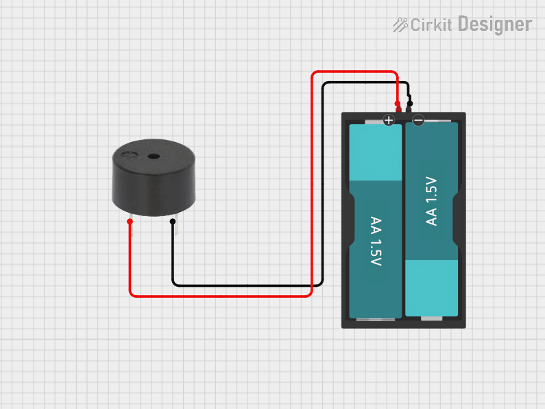
- Power Supply: Connect the positive pin of the buzzer to a voltage source (3.3V to 5V) and the negative pin to the ground (GND).
- Control with Microcontroller: To control the buzzer with a microcontroller (e.g., Arduino), connect the positive pin to a digital output pin and the negative pin to GND.
- Signal Input: The buzzer will produce sound when a HIGH signal (logic 1) is applied to the positive pin.
Important Considerations and Best Practices
- Voltage Range: Ensure the operating voltage is within the specified range (3.3V to 5V) to avoid damage.
- Polarity: Observe correct polarity when connecting the buzzer. Reversing the connections may damage the component.
- Mounting: Secure the buzzer in place to prevent vibrations or movement during operation.
- Continuous Use: Avoid running the buzzer continuously for extended periods at maximum voltage to prolong its lifespan.
Example: Using the Key Studo Buzzer with Arduino UNO
The following example demonstrates how to use the Key Studo Buzzer with an Arduino UNO to produce a simple beeping sound.
// Example: Key Studo Buzzer with Arduino UNO
// This code generates a beeping sound using the Key Studo Buzzer.

const int buzzerPin = 8; // Connect the positive pin of the buzzer to digital pin 8

void setup() {
  pinMode(buzzerPin, OUTPUT); // Set the buzzer pin as an output
}

void loop() {
  digitalWrite(buzzerPin, HIGH); // Turn the buzzer ON
  delay(500); // Wait for 500 milliseconds
  digitalWrite(buzzerPin, LOW); // Turn the buzzer OFF
  delay(500); // Wait for 500 milliseconds
}
Notes:
- Adjust the
delay()values to change the beep duration and interval. - Ensure the buzzer is securely connected to avoid loose connections.
Troubleshooting and FAQs
Common Issues and Solutions
No Sound from the Buzzer
- Cause: Incorrect wiring or insufficient voltage.
- Solution: Verify the connections and ensure the voltage is within the specified range (3.3V to 5V).
Buzzer Produces Weak or Distorted Sound
- Cause: Low input voltage or poor connections.
- Solution: Check the power supply and ensure secure connections.
Buzzer Overheats
- Cause: Exceeding the maximum voltage or prolonged continuous use.
- Solution: Reduce the input voltage and avoid running the buzzer continuously at maximum voltage.
Buzzer Does Not Respond to Microcontroller Signals
- Cause: Incorrect pin configuration or faulty code.
- Solution: Verify the pin connections and ensure the code is correctly written and uploaded.
FAQs
Q1: Can I use the Key Studo Buzzer with a 3.3V microcontroller?
A1: Yes, the buzzer operates within a voltage range of 3.3V to 5V, making it compatible with 3.3V microcontrollers.
Q2: Is the Key Studo Buzzer waterproof?
A2: No, the buzzer is not waterproof. Avoid exposing it to moisture or water.
Q3: Can I control the buzzer's sound frequency?
A3: No, the Key Studo Buzzer is an active buzzer with a fixed frequency (~2 kHz). For variable frequencies, use a passive buzzer.
Q4: How far can the sound of the buzzer be heard?
A4: The buzzer produces a sound pressure level of ≥ 85 dB at 10 cm, which is audible over a reasonable distance in quiet environments.