How to Use 1 Channel Relay 5V: Examples, Pinouts, and Specs
1 Channel Relay 5V Module Documentation
1. Introduction
The 1 Channel Relay 5V Module is an electromechanical switch that allows a low-voltage control signal (e.g., from a microcontroller like an Arduino) to control a higher voltage circuit. This module is widely used in automation, home appliances, and industrial control systems to safely isolate and switch high-power devices such as lights, fans, motors, and other electrical loads.
Common Applications:
- Home automation (e.g., controlling lights or appliances)
- Industrial control systems
- IoT projects
- Motor control
- Smart home devices
- Security systems (e.g., activating alarms or locks)
The relay module provides electrical isolation between the control circuit and the high-power circuit, ensuring safety and reliability in your projects.
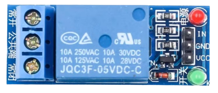
2. Technical Specifications
The following table outlines the key technical details of the 1 Channel Relay 5V Module:
| Parameter | Specification |
|---|---|
| Operating Voltage | 5V DC |
| Trigger Voltage | 3.3V to 5V DC |
| Maximum Load Voltage | 250V AC / 30V DC |
| Maximum Load Current | 10A (AC) / 10A (DC) |
| Relay Type | SPDT (Single Pole Double Throw) |
| Isolation | Optocoupler-based isolation between control and load |
| Dimensions | ~50mm x 26mm x 18mm |
| Weight | ~15g |
Pin Configuration and Descriptions
| Pin Name | Type | Description |
|---|---|---|
| VCC | Power Input | Connect to 5V DC power supply. |
| GND | Ground | Connect to the ground of the power supply or microcontroller. |
| IN | Control Signal | Input pin to control the relay. A HIGH signal activates the relay. |
| COM | Common | Common terminal of the relay switch. |
| NO | Normally Open | Normally open terminal. Connect the load here if you want it to be OFF by default. |
| NC | Normally Closed | Normally closed terminal. Connect the load here if you want it to be ON by default. |
3. Usage Instructions
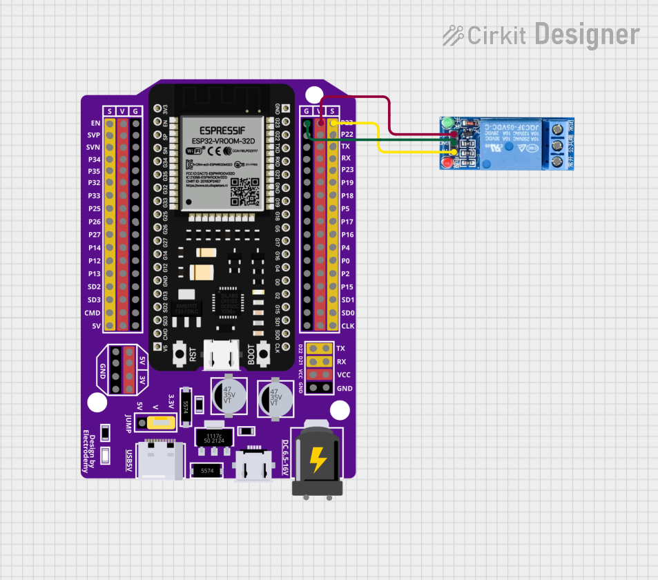
Connecting the Relay Module to an Arduino UNO
Below is a step-by-step guide to using the 1 Channel Relay 5V Module with an Arduino UNO:
Wiring the Relay Module:
- Connect the VCC pin of the relay module to the 5V pin on the Arduino.
- Connect the GND pin of the relay module to the GND pin on the Arduino.
- Connect the IN pin of the relay module to a digital I/O pin on the Arduino (e.g., pin 7).
Connecting the Load:
- Identify the load you want to control (e.g., a light bulb or fan).
- Connect one terminal of the load to the COM pin of the relay.
- Connect the other terminal of the load to the power source (e.g., 220V AC or 12V DC).
- Connect the NO or NC pin of the relay to the power source, depending on whether you want the load to be OFF or ON by default.
Programming the Arduino:
- Use the Arduino IDE to write a program that controls the relay module.
- Upload the program to the Arduino UNO.
Example Arduino Code
// Example code to control a 1 Channel Relay 5V Module with an Arduino UNO

// Define the pin connected to the relay module
const int relayPin = 7;

void setup() {
  // Set the relay pin as an output
  pinMode(relayPin, OUTPUT);

  // Ensure the relay is OFF at startup
  digitalWrite(relayPin, LOW);
}

void loop() {
  // Turn the relay ON (activates the connected load)
  digitalWrite(relayPin, HIGH);
  delay(5000); // Keep the relay ON for 5 seconds

  // Turn the relay OFF (deactivates the connected load)
  digitalWrite(relayPin, LOW);
  delay(5000); // Keep the relay OFF for 5 seconds
}
Important Considerations:
- Power Supply: Ensure the relay module is powered with a stable 5V DC supply.
- Load Ratings: Do not exceed the maximum voltage and current ratings of the relay (250V AC / 30V DC, 10A).
- Isolation: The relay module provides electrical isolation, but always handle high-voltage circuits with care.
- Flyback Diode: If controlling an inductive load (e.g., a motor), use a flyback diode across the load to protect the relay from voltage spikes.
4. Troubleshooting and FAQs
Common Issues and Solutions
| Issue | Possible Cause | Solution |
|---|---|---|
| Relay does not activate | Insufficient control signal voltage | Ensure the control signal is between 3.3V and 5V. |
| Relay activates but load does not work | Incorrect wiring of the load | Double-check the wiring of the COM, NO, and NC terminals. |
| Relay module overheats | Exceeding the load current or voltage rating | Ensure the load does not exceed 10A or 250V AC / 30V DC. |
| Arduino resets when relay activates | Power supply issue or back EMF from load | Use a separate power supply for the relay module or add a flyback diode. |
Frequently Asked Questions (FAQs)
Can I use the relay module with a 3.3V microcontroller?
- Yes, the relay module can be triggered with a 3.3V control signal, but ensure the power supply to the module is 5V.
Can I control multiple relays with one Arduino?
- Yes, you can control multiple relays by connecting each relay's IN pin to a separate digital I/O pin on the Arduino.
Is the relay module safe for high-voltage applications?
- Yes, the relay module is designed for high-voltage applications, but always follow proper safety precautions when working with high voltages.
What is the difference between the NO and NC terminals?
- The NO (Normally Open) terminal is disconnected from the COM terminal when the relay is OFF. The NC (Normally Closed) terminal is connected to the COM terminal when the relay is OFF.
This documentation provides a comprehensive guide to using the 1 Channel Relay 5V Module. Whether you're a beginner or an experienced user, this guide will help you integrate the relay module into your projects safely and effectively.
Explore Projects Built with 1 Channel Relay 5V


Explore Projects Built with 1 Channel Relay 5V