How to Use pi manual: Examples, Pinouts, and Specs
Introduction
- The Raspberry Pi Manual is a comprehensive guide designed to help users set up, program, and troubleshoot their Raspberry Pi devices. It provides step-by-step instructions, technical insights, and practical examples to ensure users can maximize the potential of their Raspberry Pi.
- Common applications include:
- Setting up a Raspberry Pi for the first time.
- Learning programming languages like Python.
- Building DIY electronics projects.
- Troubleshooting hardware and software issues.
Explore Projects Built with pi manual

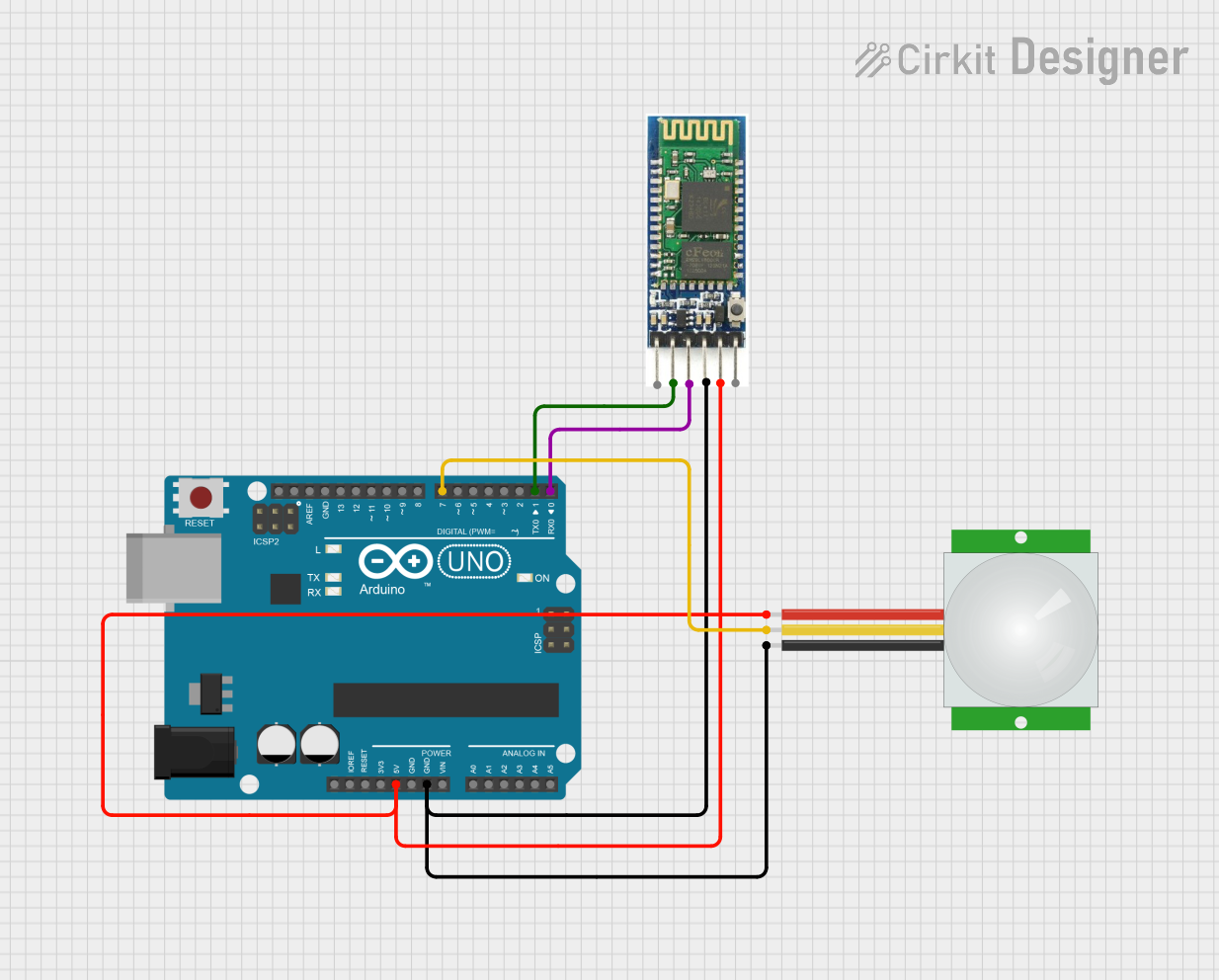

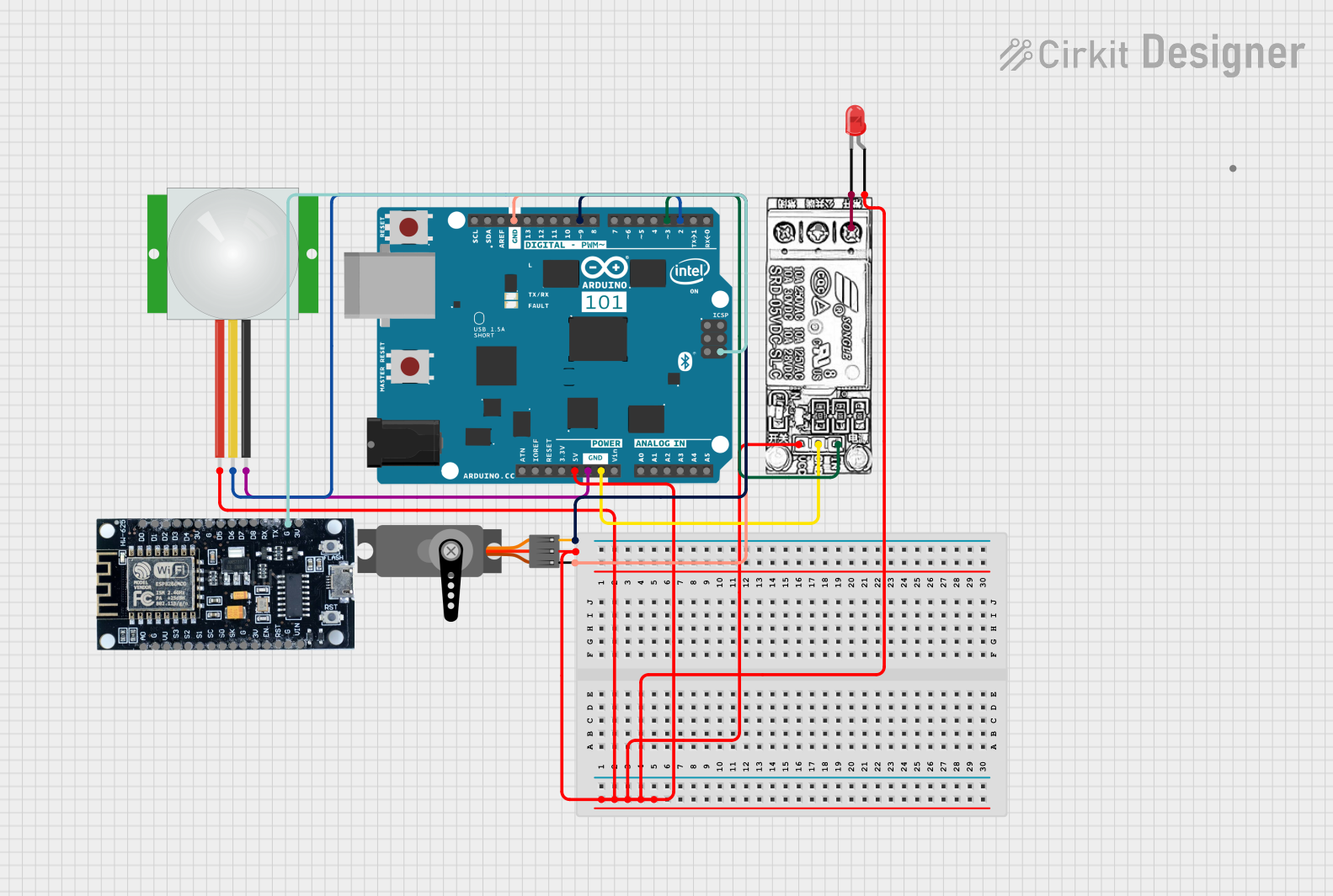
Explore Projects Built with pi manual
Technical Specifications
While the Raspberry Pi Manual is not an electronic component, it provides detailed information about the Raspberry Pi hardware and software. Below is an overview of the Raspberry Pi's key technical specifications, which are often referenced in the manual:
Raspberry Pi 4 Model B Specifications
| Specification | Details |
|---|---|
| Processor | Quad-core Cortex-A72 (ARM v8) 64-bit SoC @ 1.5GHz |
| RAM Options | 2GB, 4GB, or 8GB LPDDR4 |
| USB Ports | 2 × USB 3.0, 2 × USB 2.0 |
| GPIO Pins | 40-pin header (2 × 20) |
| Video Output | 2 × micro-HDMI ports (up to 4K resolution) |
| Networking | Gigabit Ethernet, 802.11ac Wi-Fi, Bluetooth 5.0 |
| Power Supply | 5V/3A via USB-C |
| Storage | microSD card slot |
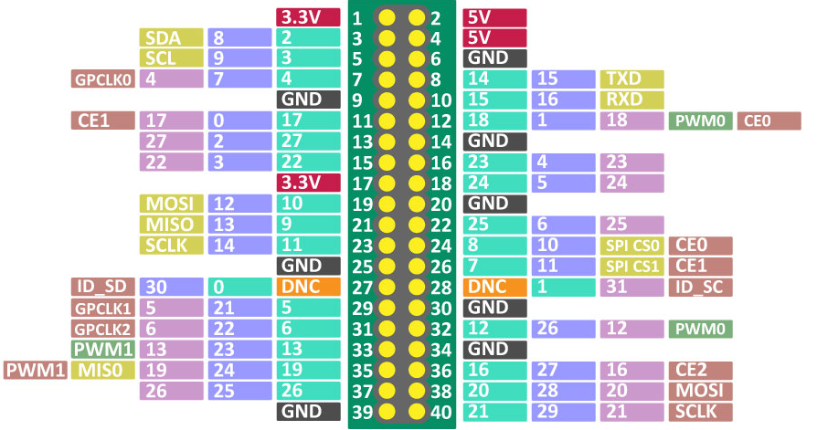
GPIO Pin Configuration
The Raspberry Pi Manual includes a detailed GPIO pinout diagram. Below is a simplified table of the GPIO pin configuration:
| Pin Number | Pin Name | Function |
|---|---|---|
| 1 | 3.3V Power | Power Supply |
| 2 | 5V Power | Power Supply |
| 3 | GPIO 2 (SDA1) | I2C Data Line |
| 4 | 5V Power | Power Supply |
| 5 | GPIO 3 (SCL1) | I2C Clock Line |
| 6 | Ground | Ground |
| ... | ... | ... |
For a complete GPIO pinout, refer to the Raspberry Pi Manual.
Usage Instructions
Setting Up the Raspberry Pi
Prepare the Hardware:
- Insert a microSD card with the Raspberry Pi OS installed.
- Connect peripherals (keyboard, mouse, monitor).
- Plug in the power supply.
Boot the Raspberry Pi:
- Power on the Raspberry Pi and follow the on-screen setup instructions.
- Configure Wi-Fi, language, and update the software.
Access the GPIO Pins:
- Use jumper wires to connect external components like LEDs, sensors, or motors.
- Ensure proper pin connections to avoid damage.
Programming the Raspberry Pi
The Raspberry Pi Manual provides examples for programming in Python. Below is a simple example to blink an LED connected to GPIO pin 17:
Import the necessary library for GPIO control
import RPi.GPIO as GPIO import time
Set up GPIO mode and pin
GPIO.setmode(GPIO.BCM) # Use Broadcom pin numbering GPIO.setup(17, GPIO.OUT) # Set GPIO pin 17 as an output
try: while True: GPIO.output(17, GPIO.HIGH) # Turn on the LED time.sleep(1) # Wait for 1 second GPIO.output(17, GPIO.LOW) # Turn off the LED time.sleep(1) # Wait for 1 second except KeyboardInterrupt: # Clean up GPIO settings when the program is interrupted GPIO.cleanup()
Best Practices
- Always shut down the Raspberry Pi properly to avoid corrupting the microSD card.
- Use a high-quality power supply to ensure stable operation.
- Double-check GPIO connections to prevent short circuits.
Troubleshooting and FAQs
Common Issues
The Raspberry Pi does not boot:
- Ensure the microSD card is properly inserted and contains a valid OS image.
- Check the power supply for sufficient voltage and current.
No display on the monitor:
- Verify the HDMI cable is securely connected.
- Ensure the monitor is set to the correct input source.
GPIO pins not working:
- Confirm the correct GPIO pin numbering (BCM vs. BOARD mode).
- Check for loose or incorrect connections.
Solutions and Tips
Updating the Raspberry Pi OS: Run the following commands in the terminal to update the OS:
sudo apt update
sudo apt full-upgrade
Resetting the Raspberry Pi: If the device becomes unresponsive, disconnect the power supply, wait a few seconds, and reconnect it.
Using the Raspberry Pi Manual: Refer to the troubleshooting section for detailed solutions to hardware and software issues.
By following the Raspberry Pi Manual, users can confidently set up, program, and troubleshoot their Raspberry Pi devices for a wide range of applications.