Cirkit Designer Logo
Cirkit Designer
Your all-in-one circuit design IDE
Home / 
Component Documentation

How to Use SparkFun RedBoard Turbo: Examples, Pinouts, and Specs

Image of SparkFun RedBoard Turbo
Cirkit Designer LogoDesign with SparkFun RedBoard Turbo in Cirkit Designer

Introduction

The SparkFun RedBoard Turbo is an advanced development board based on the ATmega328P microcontroller. It is designed to be a drop-in replacement for the Arduino Uno with a form factor and pinout that are familiar to users of the classic Arduino boards. However, the RedBoard Turbo comes with additional features and improved performance, making it suitable for a wide range of applications from rapid prototyping to final product integration.

Common applications for the SparkFun RedBoard Turbo include:

  • Educational projects and learning platforms for electronics and programming.
  • DIY electronics for hobbyists, including home automation and robotics.
  • Prototyping for industrial applications and IoT devices.
  • Custom embedded systems development.

Explore Projects Built with SparkFun RedBoard Turbo

Use Cirkit Designer to design, explore, and prototype these projects online. Some projects support real-time simulation. Click "Open Project" to start designing instantly!
SparkFun RedBoard Controlled Multi-Servo Circuit
Image of Sassy-Display: A project utilizing SparkFun RedBoard Turbo in a practical application
This circuit consists of a SparkFun RedBoard, which is an Arduino-compatible development platform, connected to four servo motors. The RedBoard provides 5V power and ground to each servo, and it also controls the servos using PWM signals on pins D3, D4, D5, and D6. The purpose of this circuit is to independently control the position or speed of four servos, commonly used in robotics and RC applications.
Cirkit Designer LogoOpen Project in Cirkit Designer
Bluetooth-Controlled Multi-Function Arduino Nano Gadget
Image of Copy of Smarttt: A project utilizing SparkFun RedBoard Turbo in a practical application
This is a portable, microcontroller-driven interactive device featuring Bluetooth connectivity, visual (RGB LED), auditory (loudspeaker), and haptic (vibration motor) feedback, user input (pushbutton), and a rechargeable power system (TP4056 with Li-ion battery).
Cirkit Designer LogoOpen Project in Cirkit Designer
ATmega328P-Based Sensor Hub with OLED Display and LIDAR
Image of TILTPCB: A project utilizing SparkFun RedBoard Turbo in a practical application
This circuit features an Mtiny Uno ATmega328P microcontroller as its central processing unit, interfacing with a variety of sensors and peripherals. It includes a 0.96" OLED display and an MPU6050 accelerometer/gyroscope for user interface and motion sensing, respectively. The circuit also integrates a TF LUNA LIDAR for distance measurement, a DHT11 sensor for temperature and humidity readings, and uses a 9V battery with a 7805 voltage regulator for power management. Communication with a computer for programming and data exchange is facilitated by an Adafruit FTDI Friend module.
Cirkit Designer LogoOpen Project in Cirkit Designer
WiFi-Enabled Environmental Monitoring System with Alert Notifications
Image of GAS LEAKAGE DETECTION: A project utilizing SparkFun RedBoard Turbo in a practical application
This circuit features a NUCLEO-F303RE microcontroller board interfaced with several modules for sensing, actuation, and communication. It uses I2C communication to display data on an LCD screen, UART communication to interface with an ESP8266 WiFi module, and reads an MQ-2 gas sensor via an ADC pin. The microcontroller also controls a buzzer for audible alerts and a relay module for switching higher power loads, possibly in response to sensor readings or remote commands received over WiFi.
Cirkit Designer LogoOpen Project in Cirkit Designer

Explore Projects Built with SparkFun RedBoard Turbo

Use Cirkit Designer to design, explore, and prototype these projects online. Some projects support real-time simulation. Click "Open Project" to start designing instantly!
Image of Sassy-Display: A project utilizing SparkFun RedBoard Turbo in a practical application
SparkFun RedBoard Controlled Multi-Servo Circuit
This circuit consists of a SparkFun RedBoard, which is an Arduino-compatible development platform, connected to four servo motors. The RedBoard provides 5V power and ground to each servo, and it also controls the servos using PWM signals on pins D3, D4, D5, and D6. The purpose of this circuit is to independently control the position or speed of four servos, commonly used in robotics and RC applications.
Cirkit Designer LogoOpen Project in Cirkit Designer
Image of Copy of Smarttt: A project utilizing SparkFun RedBoard Turbo in a practical application
Bluetooth-Controlled Multi-Function Arduino Nano Gadget
This is a portable, microcontroller-driven interactive device featuring Bluetooth connectivity, visual (RGB LED), auditory (loudspeaker), and haptic (vibration motor) feedback, user input (pushbutton), and a rechargeable power system (TP4056 with Li-ion battery).
Cirkit Designer LogoOpen Project in Cirkit Designer
Image of TILTPCB: A project utilizing SparkFun RedBoard Turbo in a practical application
ATmega328P-Based Sensor Hub with OLED Display and LIDAR
This circuit features an Mtiny Uno ATmega328P microcontroller as its central processing unit, interfacing with a variety of sensors and peripherals. It includes a 0.96" OLED display and an MPU6050 accelerometer/gyroscope for user interface and motion sensing, respectively. The circuit also integrates a TF LUNA LIDAR for distance measurement, a DHT11 sensor for temperature and humidity readings, and uses a 9V battery with a 7805 voltage regulator for power management. Communication with a computer for programming and data exchange is facilitated by an Adafruit FTDI Friend module.
Cirkit Designer LogoOpen Project in Cirkit Designer
Image of GAS LEAKAGE DETECTION: A project utilizing SparkFun RedBoard Turbo in a practical application
WiFi-Enabled Environmental Monitoring System with Alert Notifications
This circuit features a NUCLEO-F303RE microcontroller board interfaced with several modules for sensing, actuation, and communication. It uses I2C communication to display data on an LCD screen, UART communication to interface with an ESP8266 WiFi module, and reads an MQ-2 gas sensor via an ADC pin. The microcontroller also controls a buzzer for audible alerts and a relay module for switching higher power loads, possibly in response to sensor readings or remote commands received over WiFi.
Cirkit Designer LogoOpen Project in Cirkit Designer

Technical Specifications

Key Technical Details

  • Microcontroller: ATmega328P
  • Operating Voltage: 5V
  • Input Voltage (recommended): 7-15V
  • Input Voltage (limits): 6-20V
  • Digital I/O Pins: 14 (of which 6 provide PWM output)
  • Analog Input Pins: 6
  • DC Current per I/O Pin: 40 mA
  • DC Current for 3.3V Pin: 150 mA
  • Flash Memory: 32 KB (ATmega328P) of which 0.5 KB used by bootloader
  • SRAM: 2 KB (ATmega328P)
  • EEPROM: 1 KB (ATmega328P)
  • Clock Speed: 16 MHz

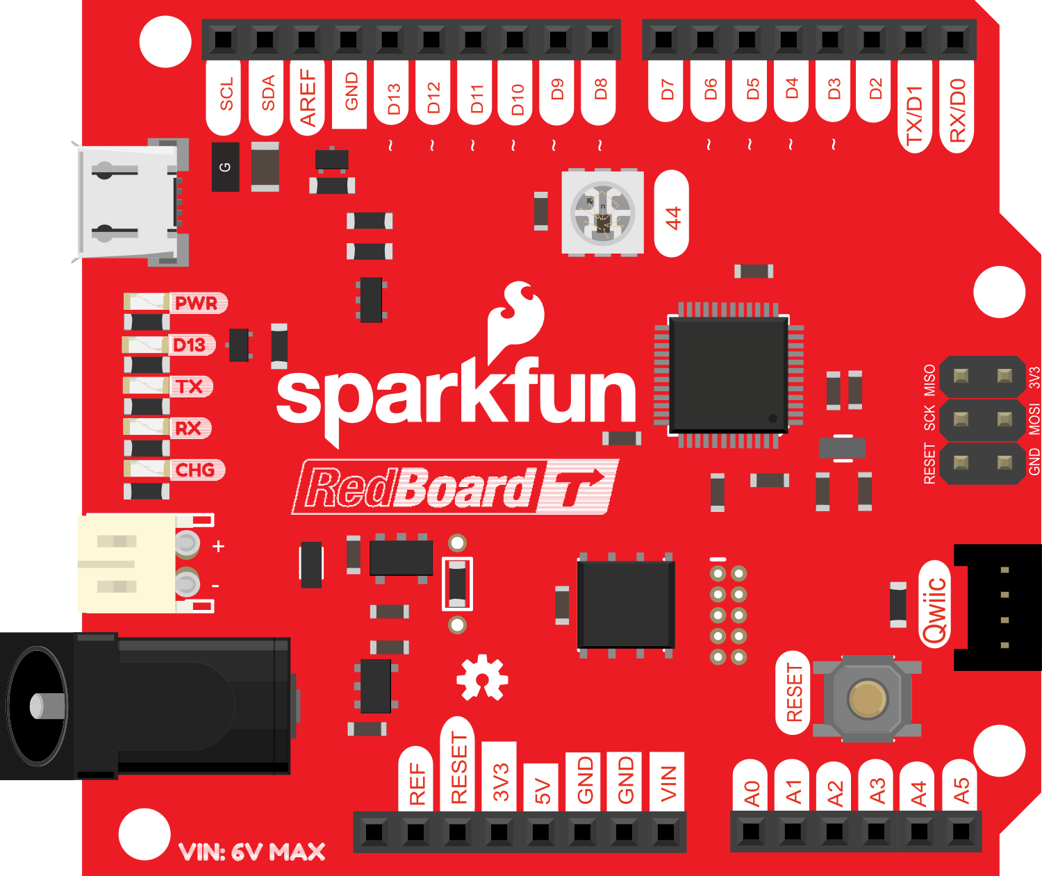
Pin Configuration and Descriptions

Pin Number Function Description
1 RESET Used to reset the microcontroller
2-13 Digital I/O Digital input/output pins, PWM on 3, 5, 6, 9, 10, 11
14-19 Analog Input Analog input pins A0-A5
20, 21 I2C SDA and SCL for I2C communication
22, 23 TX/RX Serial communication pins
24 3.3V 3.3V power output (up to 150 mA)
25 5V 5V power output (from regulator)
26 GND Ground
27 Vin Input voltage to the board
28 AREF Analog reference voltage for the ADC

Usage Instructions

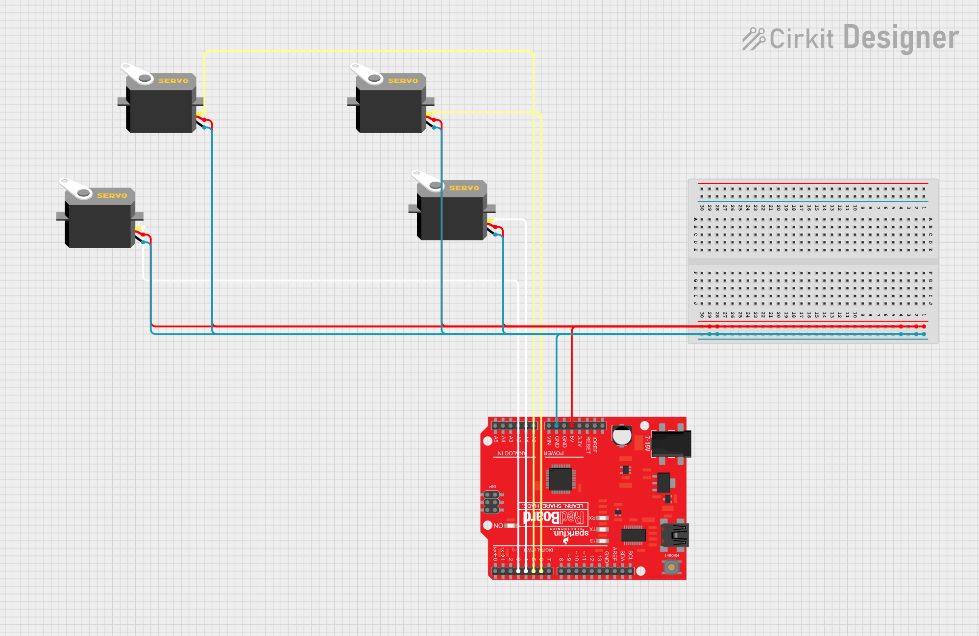
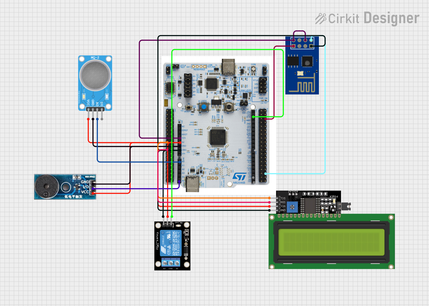
Integrating with a Circuit

To use the SparkFun RedBoard Turbo in a circuit:

  1. Connect the board to a power source within the recommended voltage range (7-15V).
  2. Use the digital and analog pins to interface with sensors, actuators, and other components.
  3. Ensure that the current draw from each I/O pin does not exceed 40 mA.
  4. Utilize the 3.3V or 5V output pins to power external components, keeping in mind the current limitations.

Programming the Board

The RedBoard Turbo can be programmed using the Arduino IDE:

  1. Download and install the Arduino IDE from the official Arduino website.
  2. Connect the RedBoard Turbo to your computer using a USB cable.
  3. Select "Arduino/Genuino Uno" from the Board menu in the IDE.
  4. Write your sketch (program) and upload it to the board using the IDE.

Best Practices

  • Always disconnect the board from the power source before making or altering connections.
  • Use a current-limiting resistor with LEDs and other sensitive components.
  • Avoid exposing the board to static discharge, moisture, or extreme temperatures.

Example Code for Arduino UNO

// Blink an LED connected to pin 13

void setup() {
  pinMode(13, OUTPUT); // Set pin 13 as an output
}

void loop() {
  digitalWrite(13, HIGH); // Turn the LED on
  delay(1000);            // Wait for a second
  digitalWrite(13, LOW);  // Turn the LED off
  delay(1000);            // Wait for a second
}

Troubleshooting and FAQs

Common Issues

  • Board not recognized by the computer: Ensure the USB cable is properly connected and the correct drivers are installed.
  • Sketch not uploading: Check the board and port selections in the Arduino IDE. Ensure the bootloader is functioning correctly.
  • Unexpected behavior in circuits: Verify all connections, and ensure power supply voltages are within specified limits.

Solutions and Tips

  • If the board is not recognized, try a different USB cable or port, and reinstall the drivers if necessary.
  • For upload issues, double-check the selected board in the IDE and try pressing the reset button on the board just before uploading.
  • Use a multimeter to check voltages and continuity in your circuit if you encounter unexpected behavior.

FAQs

Q: Can I power the RedBoard Turbo using the USB port? A: Yes, the board can be powered through the USB connection when connected to a computer or USB power source.

Q: Is the RedBoard Turbo compatible with all Arduino Uno shields? A: Most shields designed for the Arduino Uno should be compatible with the RedBoard Turbo, but always check the voltage and pinout requirements of the shield.

Q: What is the maximum current the 3.3V pin can provide? A: The 3.3V pin can provide up to 150 mA of current.

Q: How do I reset the board? A: You can reset the board by pressing the onboard reset button or by connecting the RESET pin to ground momentarily.