How to Use HappyModel ES900RX: Examples, Pinouts, and Specs
Introduction
The HappyModel ES900RX is a lightweight and compact 2.4GHz receiver designed for remote control applications. It is particularly well-suited for drones, RC vehicles, and other hobbyist projects requiring reliable signal reception and low latency. This receiver is part of the ExpressLRS ecosystem, which is known for its high-performance, open-source radio control systems. The ES900RX offers excellent range, fast response times, and a user-friendly setup process, making it a popular choice among enthusiasts.
Explore Projects Built with HappyModel ES900RX

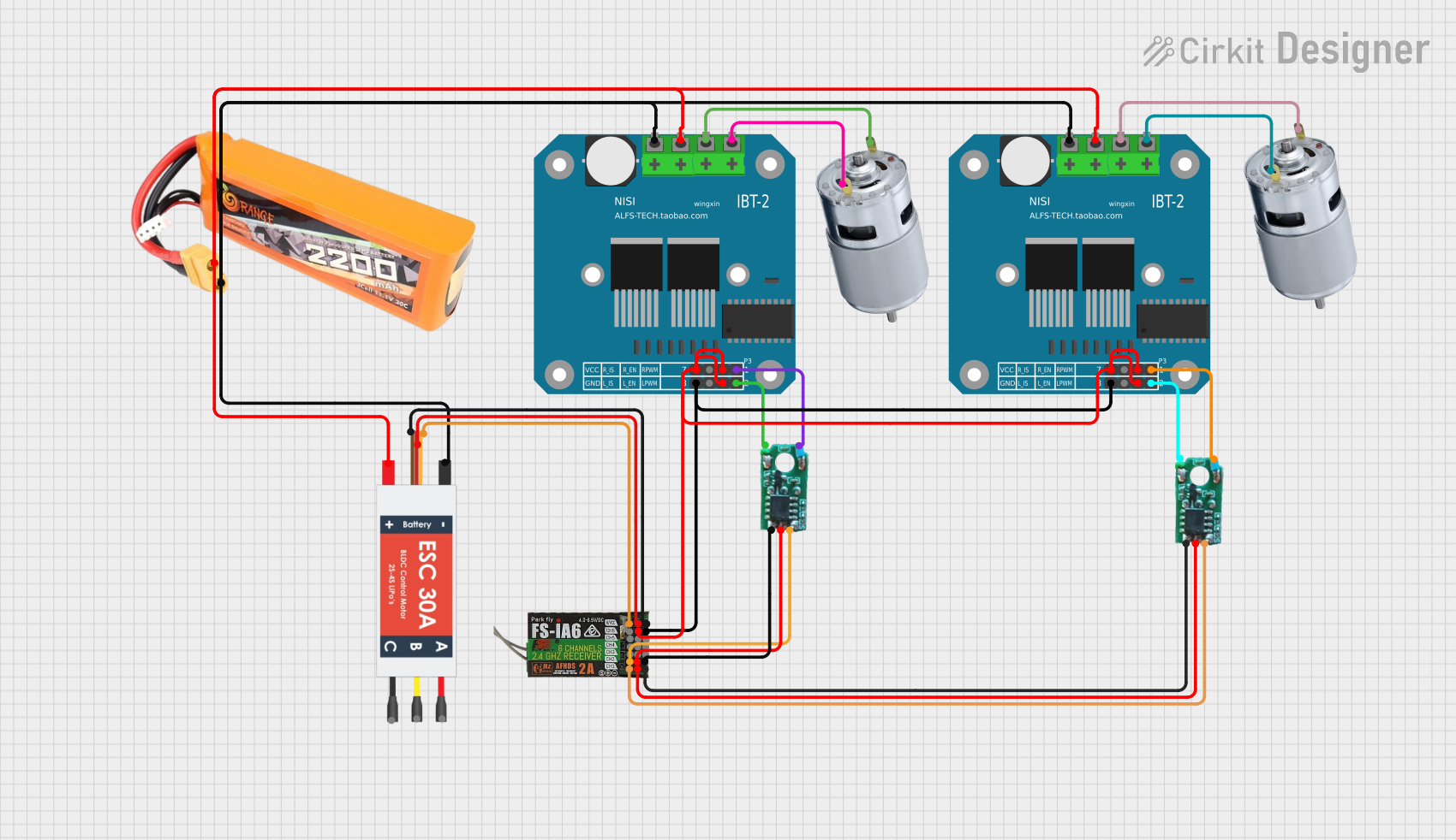

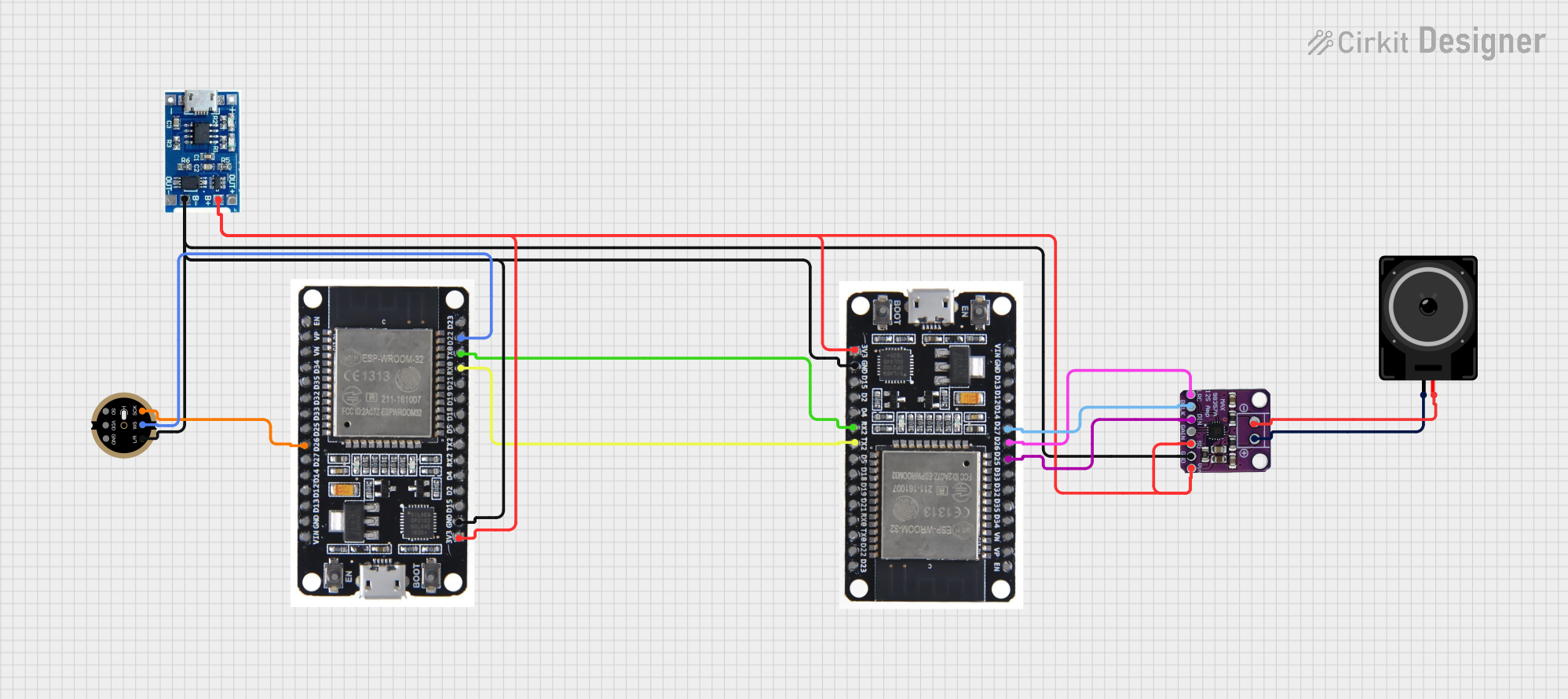
Explore Projects Built with HappyModel ES900RX
Common Applications and Use Cases
- FPV (First-Person View) drones for racing or freestyle flying
- RC cars, boats, and planes
- Robotics and other remote-controlled systems
- Projects requiring long-range, low-latency communication
Technical Specifications
The HappyModel ES900RX is designed to deliver high performance in a compact form factor. Below are its key technical details:
| Parameter | Specification |
|---|---|
| Operating Frequency | 2.4GHz |
| Protocol | ExpressLRS (Open Source) |
| Input Voltage Range | 5V (via UART connection) |
| Antenna Connector | IPEX (U.FL) |
| Dimensions | 10mm x 10mm x 3mm |
| Weight | 0.6g |
| Latency | As low as 4ms |
| Range | Up to 15km (depending on conditions) |
| Firmware Compatibility | ExpressLRS Configurator |
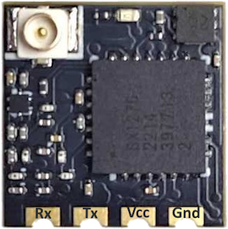
Pin Configuration and Descriptions
The ES900RX features a simple pinout for easy integration into your projects. Below is the pin configuration:
| Pin Name | Description |
|---|---|
| GND | Ground connection |
| 5V | Power input (5V) |
| TX | UART Transmit (connect to RX on flight controller) |
| RX | UART Receive (connect to TX on flight controller) |
Usage Instructions
How to Use the ES900RX in a Circuit
- Power Connection: Connect the
5Vpin to a 5V power source and theGNDpin to ground. - UART Connection: Connect the
TXpin of the ES900RX to theRXpin of your flight controller or microcontroller, and theRXpin of the ES900RX to theTXpin of your flight controller or microcontroller. - Antenna Installation: Attach the included IPEX antenna to the antenna connector for optimal signal reception.
- Binding: Follow the ExpressLRS binding procedure to pair the receiver with your transmitter. This typically involves powering on the receiver while the transmitter is in binding mode.
Important Considerations and Best Practices
- Antenna Placement: Ensure the antenna is positioned away from metal components or other sources of interference to maximize range and signal quality.
- Firmware Updates: Use the ExpressLRS Configurator to update the firmware on the ES900RX. Always ensure the firmware version matches your transmitter's firmware.
- Power Supply: Use a stable 5V power source to avoid brownouts or signal loss.
- UART Configuration: Configure the UART port on your flight controller or microcontroller to match the baud rate specified in the ExpressLRS documentation.
Example Code for Arduino UNO
While the ES900RX is typically used with flight controllers, it can also be connected to an Arduino UNO for testing or custom applications. Below is an example of how to read data from the receiver:
// Example code to read data from the ES900RX using Arduino UNO
// Connect ES900RX TX to Arduino RX (Pin 0) and ES900RX RX to Arduino TX (Pin 1)

#include <SoftwareSerial.h>

// Define RX and TX pins for SoftwareSerial
SoftwareSerial mySerial(10, 11); // RX, TX

void setup() {
  Serial.begin(9600); // Start the hardware serial for debugging
  mySerial.begin(115200); // Start the software serial for ES900RX communication

  Serial.println("ES900RX Receiver Test");
}

void loop() {
  // Check if data is available from the receiver
  if (mySerial.available()) {
    String receivedData = mySerial.readString(); // Read the incoming data
    Serial.print("Received: ");
    Serial.println(receivedData); // Print the received data to the Serial Monitor
  }
}
Notes:
- Replace
10and11inSoftwareSerialwith the pins you are using for RX and TX on the Arduino UNO. - Ensure the baud rate (
115200in this example) matches the configuration of the ES900RX.
Troubleshooting and FAQs
Common Issues and Solutions
Receiver Not Binding to Transmitter
- Ensure the receiver and transmitter are on the same firmware version.
- Verify that the receiver is in binding mode (check the LED status).
- Check for proper power supply to the receiver.
No Signal or Poor Range
- Verify that the antenna is securely connected and properly positioned.
- Avoid placing the receiver near sources of interference, such as motors or ESCs.
- Check for physical damage to the antenna or receiver.
Receiver Not Responding
- Confirm that the UART connections (TX/RX) are correct.
- Ensure the flight controller or microcontroller is configured to communicate with the receiver.
FAQs
Q: Can the ES900RX be used with any transmitter?
A: The ES900RX is compatible with transmitters running ExpressLRS firmware. Ensure both the receiver and transmitter are on compatible firmware versions.
Q: What is the maximum range of the ES900RX?
A: The range can reach up to 15km under ideal conditions, but actual range depends on factors such as antenna placement, interference, and environmental conditions.
Q: How do I update the firmware on the ES900RX?
A: Use the ExpressLRS Configurator software to flash the latest firmware. Follow the instructions provided in the ExpressLRS documentation.
Q: Can I use the ES900RX with a 3.3V power source?
A: No, the ES900RX requires a 5V power source for proper operation.
By following this documentation, you can effectively integrate the HappyModel ES900RX into your projects and troubleshoot common issues.