How to Use PR-Rotary Potentiometer: Examples, Pinouts, and Specs
Introduction
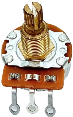
The PR-Rotary Potentiometer is a versatile variable resistor featuring a rotary knob that allows for precise adjustment of resistance within a circuit. This component is widely used in applications requiring tuning, calibration, and variable control, such as volume controls in audio equipment, light dimmers, and adjustable power supplies.
Explore Projects Built with PR-Rotary Potentiometer
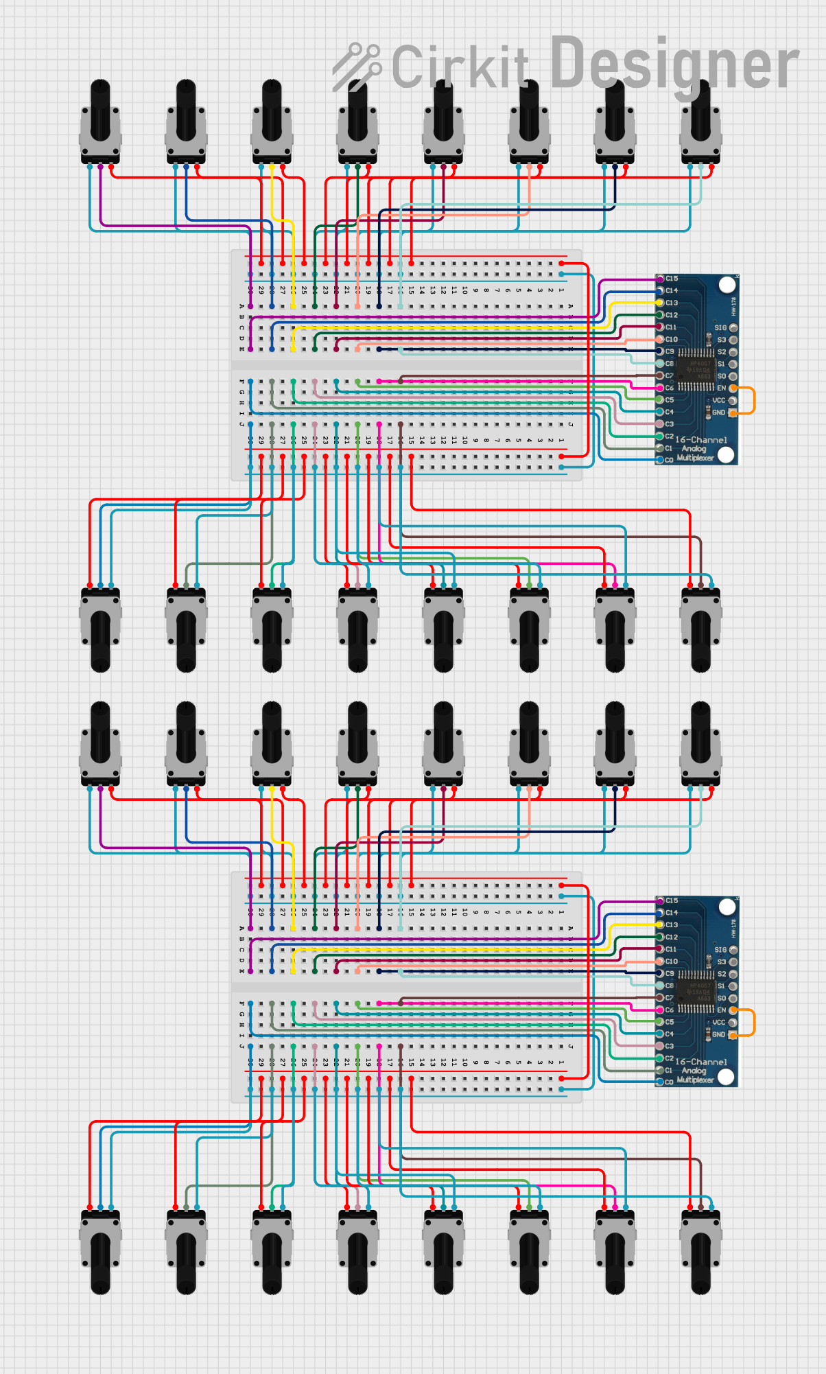


Explore Projects Built with PR-Rotary Potentiometer
Technical Specifications
Key Technical Details
| Parameter | Value |
|---|---|
| Manufacturer | PR-Rotary Potentiometer |
| Part ID | PR-Rotary Potentiometer |
| Resistance Range | 0Ω to 10kΩ |
| Tolerance | ±10% |
| Power Rating | 0.5W |
| Maximum Voltage | 250V DC |
| Operating Temperature | -40°C to +85°C |
| Rotational Life | 10,000 cycles |
Pin Configuration and Descriptions
| Pin Number | Description |
|---|---|
| 1 | Terminal 1 (Fixed end of the resistor) |
| 2 | Wiper (Variable middle terminal) |
| 3 | Terminal 2 (Fixed end of the resistor) |
Usage Instructions
How to Use the Component in a Circuit
- Identify the Pins: The potentiometer has three pins. Pin 1 and Pin 3 are the fixed ends of the resistor, and Pin 2 is the wiper, which moves along the resistive track as the knob is turned.
- Connect the Pins:
- Connect Pin 1 to the ground (GND) of your circuit.
- Connect Pin 3 to the voltage supply (Vcc).
- Connect Pin 2 to the input of the device you want to control (e.g., an analog input pin on an Arduino).
- Adjust the Resistance: Turn the rotary knob to adjust the resistance between Pin 1 and Pin 2, and between Pin 2 and Pin 3. This will vary the voltage at Pin 2, which can be read by an analog input.
Important Considerations and Best Practices
- Power Rating: Ensure that the power dissipation across the potentiometer does not exceed its rated power of 0.5W to avoid damage.
- Voltage Limits: Do not exceed the maximum voltage rating of 250V DC.
- Mechanical Stress: Avoid applying excessive force to the rotary knob to ensure the longevity of the component.
- Temperature Range: Operate the potentiometer within the specified temperature range of -40°C to +85°C.
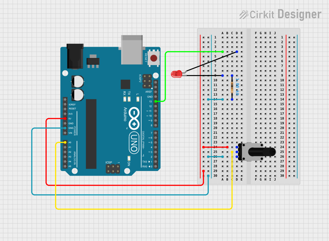
Example: Connecting to an Arduino UNO
To read the position of the potentiometer using an Arduino UNO, connect the potentiometer as follows:
- Pin 1 to GND
- Pin 3 to 5V
- Pin 2 to an analog input pin (e.g., A0)
Here is a simple Arduino code to read and display the potentiometer value:
// Define the analog pin connected to the potentiometer wiper
const int potPin = A0;

void setup() {
  // Initialize serial communication at 9600 baud rate
  Serial.begin(9600);
}

void loop() {
  // Read the analog value from the potentiometer
  int potValue = analogRead(potPin);

  // Print the potentiometer value to the serial monitor
  Serial.print("Potentiometer Value: ");
  Serial.println(potValue);

  // Wait for 100 milliseconds before the next reading
  delay(100);
}
Troubleshooting and FAQs
Common Issues Users Might Face
No Change in Output:
- Solution: Ensure that the connections are correct and secure. Verify that the potentiometer is not damaged and that the wiper is moving smoothly.
Inconsistent Readings:
- Solution: Check for loose connections or poor solder joints. Ensure that the potentiometer is within its specified operating temperature range.
Potentiometer Not Working:
- Solution: Verify that the power rating and voltage limits are not exceeded. Check for any physical damage to the potentiometer.
FAQs
Q1: Can I use the PR-Rotary Potentiometer for high-power applications?
- A1: No, the PR-Rotary Potentiometer has a power rating of 0.5W. For high-power applications, use a potentiometer with a higher power rating.
Q2: How do I clean a noisy potentiometer?
- A2: You can use a contact cleaner spray to clean the internal contacts of the potentiometer. Ensure the device is powered off before cleaning.
Q3: Can I use the potentiometer to control a digital signal?
- A3: The potentiometer is designed for analog signals. To control a digital signal, you would need an analog-to-digital converter (ADC) to interpret the potentiometer's output.
By following this documentation, users can effectively utilize the PR-Rotary Potentiometer in their electronic projects, ensuring optimal performance and longevity of the component.