Cirkit Designer Logo
Cirkit Designer
Your all-in-one circuit design IDE
Home / 
Component Documentation

How to Use X6-8: Examples, Pinouts, and Specs

Image of X6-8
Cirkit Designer LogoDesign with X6-8 in Cirkit Designer

Introduction

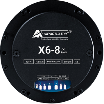
The X6-8, manufactured by Myactuator, is a versatile connector or terminal block designed for use in electronic circuits. It allows for the secure and efficient connection of multiple wires or components, making it an essential component in various applications. The X6-8 is particularly valued for its ease of assembly and disassembly, which simplifies maintenance and upgrades in complex systems.

Explore Projects Built with X6-8

Use Cirkit Designer to design, explore, and prototype these projects online. Some projects support real-time simulation. Click "Open Project" to start designing instantly!
ESP32-Based Gas Level Monitoring System with MQ6 Sensor and OLED Display
Image of gas monitor2: A project utilizing X6-8 in a practical application
This circuit features an ESP32 microcontroller interfaced with an MQ6 gas sensor, a piezo buzzer, a servo motor, an OLED display, and a SIM800L GSM module. The ESP32 reads the gas level from the MQ6 sensor and displays it on the OLED screen, while the SIM800L module enables cellular communication. The circuit is powered through a buck converter connected to a DC barrel jack, and it includes a piezo buzzer and servo motor, likely for alerting and actuation purposes in response to gas levels.
Cirkit Designer LogoOpen Project in Cirkit Designer
ESP32-Based Smart Home Automation System with Gas Detection and Servo Control
Image of PRSM: A project utilizing X6-8 in a practical application
This circuit is a multi-functional system controlled by an ESP32 microcontroller, featuring a gas sensor (MQ6) for detecting gas levels, a servo motor for mechanical movement, and a 16x2 I2C LCD for displaying information. It also includes green and red LEDs for status indication, a buzzer for audible alerts, and a 5V relay for controlling high-power devices.
Cirkit Designer LogoOpen Project in Cirkit Designer
Satellite-Based Timing and Navigation System with SDR and Atomic Clock Synchronization
Image of GPS 시스템 측정 구성도_Confirm: A project utilizing X6-8 in a practical application
This circuit appears to be a complex system involving power supply management, GPS and timing synchronization, and data communication. It includes a SI-TEX G1 Satellite Compass for GPS data, an XHTF1021 Atomic Rubidium Clock for precise timing, and Ettus USRP B200 units for software-defined radio communication. Power is supplied through various SMPS units and distributed via terminal blocks and DC jacks. Data communication is facilitated by Beelink MINI S12 N95 computers, RS232 splitters, and a 1000BASE-T Media Converter for network connectivity. RF Directional Couplers are used to interface antennas with the USRP units, and the entire system is likely contained within cases for protection and organization.
Cirkit Designer LogoOpen Project in Cirkit Designer
Arduino Mega 2560-Based Smart Home Control System with LCD Display and Flame Sensor
Image of Copy of schoolproject (1): A project utilizing X6-8 in a practical application
This circuit is a multi-functional embedded system featuring an Arduino Mega 2560 microcontroller that interfaces with a 4x4 membrane keypad, a 20x4 I2C LCD, an 8x8 LED matrix, a DS3231 RTC module, a passive buzzer, and a KY-026 flame sensor. The system is powered by a 5V PSU and is designed to provide real-time clock functionality, user input via the keypad, visual output on the LCD and LED matrix, and flame detection with an audible alert.
Cirkit Designer LogoOpen Project in Cirkit Designer

Explore Projects Built with X6-8

Use Cirkit Designer to design, explore, and prototype these projects online. Some projects support real-time simulation. Click "Open Project" to start designing instantly!
Image of gas monitor2: A project utilizing X6-8 in a practical application
ESP32-Based Gas Level Monitoring System with MQ6 Sensor and OLED Display
This circuit features an ESP32 microcontroller interfaced with an MQ6 gas sensor, a piezo buzzer, a servo motor, an OLED display, and a SIM800L GSM module. The ESP32 reads the gas level from the MQ6 sensor and displays it on the OLED screen, while the SIM800L module enables cellular communication. The circuit is powered through a buck converter connected to a DC barrel jack, and it includes a piezo buzzer and servo motor, likely for alerting and actuation purposes in response to gas levels.
Cirkit Designer LogoOpen Project in Cirkit Designer
Image of PRSM: A project utilizing X6-8 in a practical application
ESP32-Based Smart Home Automation System with Gas Detection and Servo Control
This circuit is a multi-functional system controlled by an ESP32 microcontroller, featuring a gas sensor (MQ6) for detecting gas levels, a servo motor for mechanical movement, and a 16x2 I2C LCD for displaying information. It also includes green and red LEDs for status indication, a buzzer for audible alerts, and a 5V relay for controlling high-power devices.
Cirkit Designer LogoOpen Project in Cirkit Designer
Image of GPS 시스템 측정 구성도_Confirm: A project utilizing X6-8 in a practical application
Satellite-Based Timing and Navigation System with SDR and Atomic Clock Synchronization
This circuit appears to be a complex system involving power supply management, GPS and timing synchronization, and data communication. It includes a SI-TEX G1 Satellite Compass for GPS data, an XHTF1021 Atomic Rubidium Clock for precise timing, and Ettus USRP B200 units for software-defined radio communication. Power is supplied through various SMPS units and distributed via terminal blocks and DC jacks. Data communication is facilitated by Beelink MINI S12 N95 computers, RS232 splitters, and a 1000BASE-T Media Converter for network connectivity. RF Directional Couplers are used to interface antennas with the USRP units, and the entire system is likely contained within cases for protection and organization.
Cirkit Designer LogoOpen Project in Cirkit Designer
Image of Copy of schoolproject (1): A project utilizing X6-8 in a practical application
Arduino Mega 2560-Based Smart Home Control System with LCD Display and Flame Sensor
This circuit is a multi-functional embedded system featuring an Arduino Mega 2560 microcontroller that interfaces with a 4x4 membrane keypad, a 20x4 I2C LCD, an 8x8 LED matrix, a DS3231 RTC module, a passive buzzer, and a KY-026 flame sensor. The system is powered by a 5V PSU and is designed to provide real-time clock functionality, user input via the keypad, visual output on the LCD and LED matrix, and flame detection with an audible alert.
Cirkit Designer LogoOpen Project in Cirkit Designer

Common Applications and Use Cases

  • Industrial control systems
  • Home automation projects
  • Robotics and mechatronics
  • Prototyping and testing circuits
  • Power distribution in electronic devices

Technical Specifications

The X6-8 connector is designed to meet the needs of a wide range of electronic applications. Below are its key technical details:

General Specifications

Parameter Value
Manufacturer Myactuator
Type Terminal Block / Connector
Number of Terminals 8
Rated Voltage 300V
Rated Current 15A
Wire Size Compatibility 22-12 AWG
Material Flame-retardant plastic (UL94-V0)
Operating Temperature -40°C to +105°C
Mounting Type Screw or PCB mount

Pin Configuration and Descriptions

The X6-8 features 8 terminals, each designed for secure wire connections. Below is a description of the pin layout:

Pin Number Description
1-8 Wire connection terminals
Ground Pin Optional grounding terminal

Usage Instructions

The X6-8 connector is straightforward to use and can be integrated into a variety of circuits. Follow the steps below for proper usage:

Connecting Wires

  1. Prepare the Wires: Strip the insulation from the ends of the wires to expose approximately 5-7 mm of conductor.
  2. Insert the Wires: Loosen the screws on the X6-8 terminals, insert the stripped wire ends into the terminal slots, and tighten the screws securely.
  3. Verify Connections: Ensure that the wires are firmly held in place and that there is no exposed conductor outside the terminal block.

Mounting the Connector

  • For PCB Mounting: Solder the X6-8 connector onto the designated pads on the PCB.
  • For Screw Mounting: Use screws to attach the connector to a panel or enclosure.

Important Considerations

  • Avoid exceeding the rated voltage and current to prevent overheating or damage.
  • Ensure proper insulation of wires to avoid short circuits.
  • Use a screwdriver of the appropriate size to avoid damaging the screws.

Example: Connecting to an Arduino UNO

The X6-8 can be used to connect external components, such as sensors or actuators, to an Arduino UNO. Below is an example of how to use the X6-8 for connecting a 12V motor:
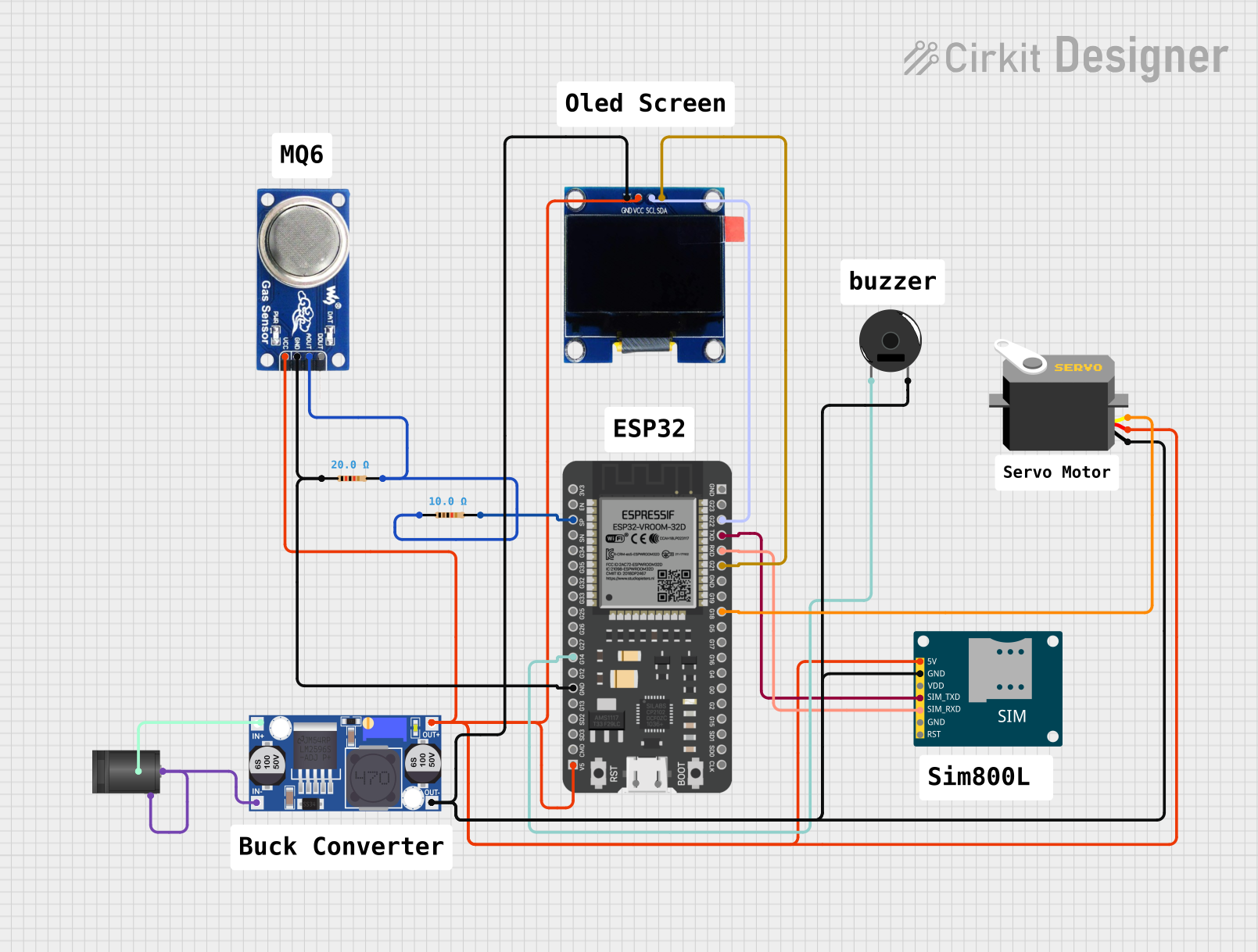
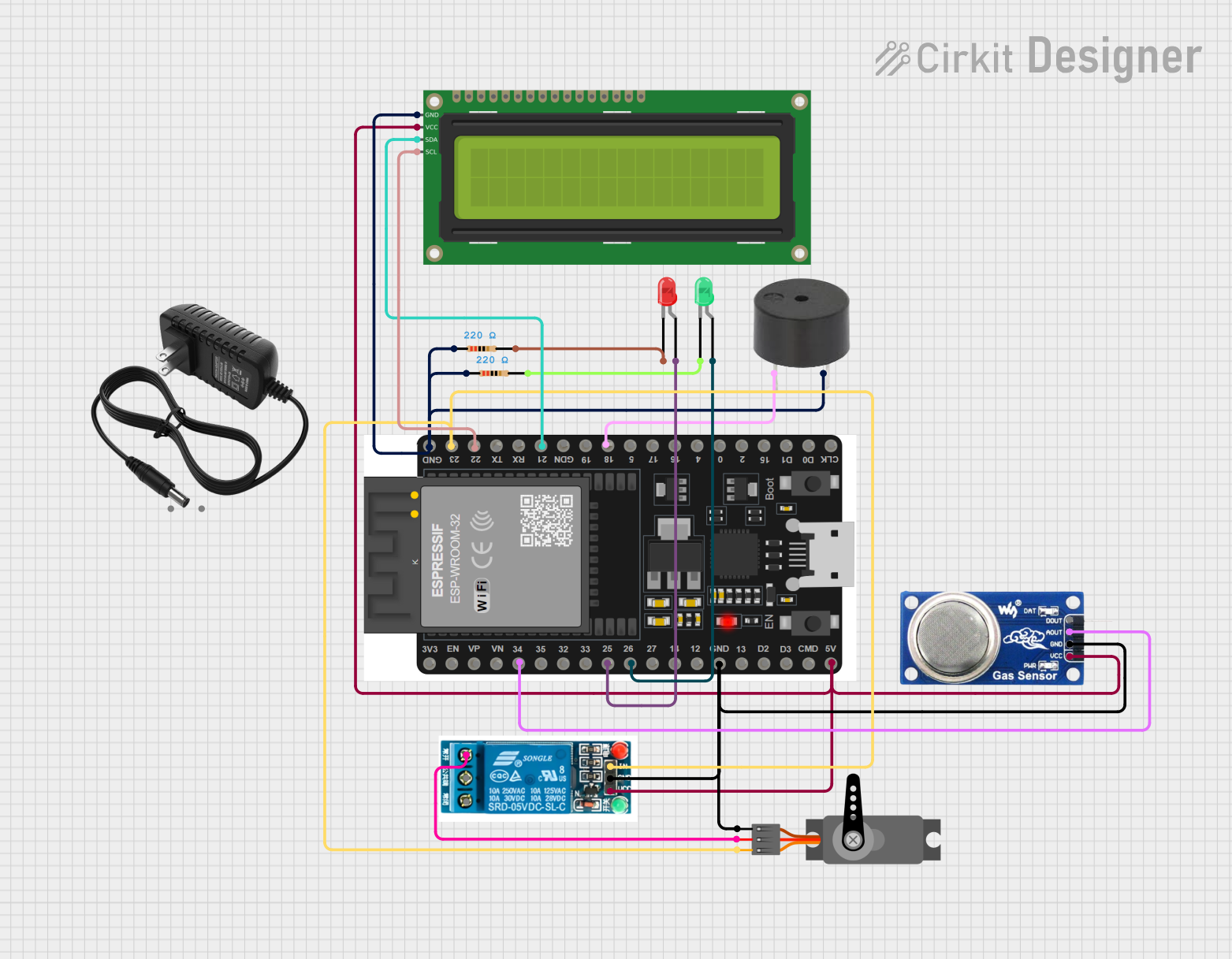
Circuit Diagram

  • Connect the motor's positive and negative terminals to two terminals on the X6-8.
  • Use jumper wires to connect the corresponding terminals on the X6-8 to the Arduino's motor driver module.

Arduino Code

// Example code to control a motor connected via the X6-8 connector
const int motorPin = 9; // Pin connected to the motor driver

void setup() {
  pinMode(motorPin, OUTPUT); // Set motor pin as output
}

void loop() {
  digitalWrite(motorPin, HIGH); // Turn the motor ON
  delay(1000); // Run for 1 second
  digitalWrite(motorPin, LOW); // Turn the motor OFF
  delay(1000); // Wait for 1 second
}

Troubleshooting and FAQs

Common Issues

  1. Loose Connections

    • Cause: Screws not tightened properly.
    • Solution: Re-tighten the screws and ensure the wires are securely held.
  2. Overheating

    • Cause: Exceeding the rated current or voltage.
    • Solution: Verify that the connected load is within the specified limits.
  3. Wire Slippage

    • Cause: Insufficient wire stripping or improper insertion.
    • Solution: Strip the wire to the recommended length and reinsert it.
  4. Short Circuits

    • Cause: Exposed conductors touching each other.
    • Solution: Ensure proper insulation and spacing between wires.

FAQs

Q: Can the X6-8 be used for high-frequency signals?
A: The X6-8 is primarily designed for power and low-frequency signal connections. For high-frequency signals, consider using specialized connectors.

Q: Is the X6-8 suitable for outdoor use?
A: The X6-8 is not inherently weatherproof. For outdoor applications, use an enclosure to protect it from moisture and dust.

Q: Can I use the X6-8 with stranded wires?
A: Yes, the X6-8 is compatible with both solid and stranded wires. Ensure that stranded wires are properly twisted before insertion.

Q: How do I replace a damaged X6-8 connector?
A: Disconnect all wires, unscrew the mounting screws (if applicable), and replace the connector with a new one. Reconnect the wires following the usage instructions.

By following this documentation, users can effectively integrate the X6-8 connector into their projects and troubleshoot common issues with ease.