
How to Use AVR ISP 6 Pin: Examples, Pinouts, and Specs
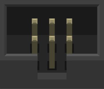
 Design with AVR ISP 6 Pin in Cirkit Designer
Introduction
The AVR ISP 6 Pin is a compact and efficient In-System Programmer (ISP) designed for programming AVR microcontrollers directly on the circuit board. This component eliminates the need to remove the microcontroller from its circuit for programming, making it ideal for development, debugging, and firmware updates. It is widely used in embedded systems, robotics, and IoT applications.
Explore Projects Built with AVR ISP 6 Pin
 Open Project in Cirkit Designer
 Open Project in Cirkit Designer
 Open Project in Cirkit Designer
 Open Project in Cirkit Designer
Explore Projects Built with AVR ISP 6 Pin
Open Project in Cirkit DesignerOpen Project in Cirkit DesignerOpen Project in Cirkit DesignerOpen Project in Cirkit DesignerCommon Applications and Use Cases
- Programming AVR microcontrollers (e.g., ATmega and ATtiny series)
- Debugging and testing embedded systems
- Updating firmware on AVR-based devices
- Prototyping and development of AVR-based projects
Technical Specifications
The AVR ISP 6 Pin follows the standard 6-pin ISP interface, which is compatible with most AVR microcontrollers. Below are the key technical details and pin configuration:
Key Technical Details
- Voltage Range: 2.7V to 5.5V (depends on the target microcontroller)
- Communication Protocol: SPI (Serial Peripheral Interface)
- Connector Type: 6-pin header (2x3 configuration)
- Programming Speed: Up to 1 MHz (adjustable based on the target device)
- Compatibility: Supports AVR microcontrollers with ISP capability
Pin Configuration and Descriptions
The 6-pin ISP header is arranged in a 2x3 configuration. The table below describes each pin:
| Pin Number | Pin Name | Description |
|---|---|---|
| 1 | MISO | Master In Slave Out (data from MCU) |
| 2 | VCC | Power supply for the target device |
| 3 | SCK | Serial Clock |
| 4 | MOSI | Master Out Slave In (data to MCU) |
| 5 | RESET | Reset line for the target MCU |
| 6 | GND | Ground connection |
Pinout Diagram
  [1] MISO   [2] VCC
  [3] SCK    [4] MOSI
  [5] RESET  [6] GND
Usage Instructions
How to Use the AVR ISP 6 Pin in a Circuit
Connect the ISP Header:
- Align the 6-pin ISP connector with the corresponding header on the target board.
- Ensure proper orientation by matching the pin labels (e.g., MISO, MOSI, etc.).
Power the Target Device:
- The target device can be powered either externally or through the ISP programmer (if supported). Ensure the voltage levels are compatible.
Connect the Programmer:
- Attach the AVR ISP programmer to the 6-pin header. Use a compatible programmer such as the AVRISP mkII or USBasp.
Program the Microcontroller:
- Use software like Atmel Studio, AVRDUDE, or Arduino IDE to upload the firmware.
- Select the correct microcontroller model and ISP programmer in the software settings.
Verify the Connection:
- Perform a connection test in the programming software to ensure proper communication.
Important Considerations and Best Practices
- Check Pin Orientation: Incorrectly connecting the ISP header can damage the microcontroller or programmer.
- Match Voltage Levels: Ensure the programmer and target device operate at the same voltage level.
- Use Short Cables: Long cables can introduce noise and affect programming reliability.
- Disable Other Peripherals: If the SPI pins are shared with other peripherals, ensure they are disabled during programming.
Example: Using AVR ISP 6 Pin with Arduino UNO
The Arduino UNO can be programmed using the AVR ISP 6 Pin interface. Below is an example of using AVRDUDE to upload firmware:
Command to upload firmware using AVRDUDE
avrdude -c usbasp -p m328p -U flash:w:firmware.hex
-c specifies the programmer (usbasp in this case)
-p specifies the microcontroller (ATmega328P for Arduino UNO)
-U specifies the memory operation (write flash with firmware.hex)
Troubleshooting and FAQs
Common Issues and Solutions
Programmer Not Detected:
- Ensure the programmer drivers are installed correctly.
- Check the USB connection and try a different port.
Target Device Not Responding:
- Verify the ISP header connections and pin orientation.
- Ensure the target device is powered and operational.
Programming Fails Midway:
- Reduce the programming speed in the software settings.
- Check for loose connections or excessive cable length.
Incorrect Firmware Upload:
- Double-check the microcontroller model and firmware file.
- Use the
-v(verbose) option in AVRDUDE to debug the issue.
FAQs
Q: Can I use the AVR ISP 6 Pin with non-AVR microcontrollers?
A: No, the AVR ISP 6 Pin is specifically designed for AVR microcontrollers that support ISP programming.
Q: What software is compatible with the AVR ISP 6 Pin?
A: Popular options include Atmel Studio, AVRDUDE, and Arduino IDE.
Q: How do I identify pin 1 on the ISP header?
A: Pin 1 is usually marked with a dot or a square pad on the PCB. Additionally, the ribbon cable often has a red stripe indicating pin 1.
Q: Can I power the target device through the ISP programmer?
A: Some programmers support powering the target device. Check the programmer's specifications to confirm.
By following this documentation, you can effectively use the AVR ISP 6 Pin for programming and debugging AVR microcontrollers.