How to Use H743 ESC: Examples, Pinouts, and Specs
Introduction
The H743 ESC (Electronic Speed Controller) is a high-performance component designed for controlling the speed and direction of brushless motors in RC vehicles, drones, and other applications requiring precise motor control. It is engineered to deliver smooth throttle response, efficient power delivery, and advanced programmability. The H743 ESC supports a wide range of battery types and includes features such as regenerative braking, thermal protection, and customizable settings to optimize performance for specific use cases.
Explore Projects Built with H743 ESC


Explore Projects Built with H743 ESC
Common Applications
- RC cars, boats, and airplanes
- Multirotor drones and UAVs
- Robotics and automation systems
- Electric skateboards and scooters
- Industrial motor control applications
Technical Specifications
Key Specifications
| Parameter | Value |
|---|---|
| Input Voltage Range | 2S–6S LiPo (7.4V–22.2V) |
| Continuous Current Rating | 40A |
| Peak Current Rating | 60A (for 10 seconds) |
| Motor Compatibility | Brushless motors (sensorless) |
| BEC Output | 5V/3A or 6V/3A (selectable) |
| PWM Frequency | 8 kHz–32 kHz |
| Weight | 25 grams |
| Dimensions | 45mm x 25mm x 10mm |
| Operating Temperature | -20°C to 85°C |
| Communication Protocols | PWM, Oneshot125, DShot150/300/600 |
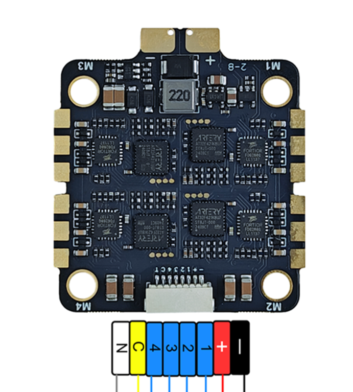
Pin Configuration
The H743 ESC typically has the following pin configuration:
| Pin Name | Description |
|---|---|
| Power Input (+) | Connect to the positive terminal of the battery. |
| Power Input (-) | Connect to the negative terminal of the battery. |
| Motor Phase A | Connect to one of the three motor wires. |
| Motor Phase B | Connect to one of the three motor wires. |
| Motor Phase C | Connect to one of the three motor wires. |
| Signal Input | Receives the PWM or digital signal from the flight controller or receiver. |
| Ground (GND) | Common ground connection for signal input. |
| BEC Output (+) | Provides regulated power to external devices (e.g., receiver, flight controller). |
| BEC Output (-) | Ground connection for the BEC output. |
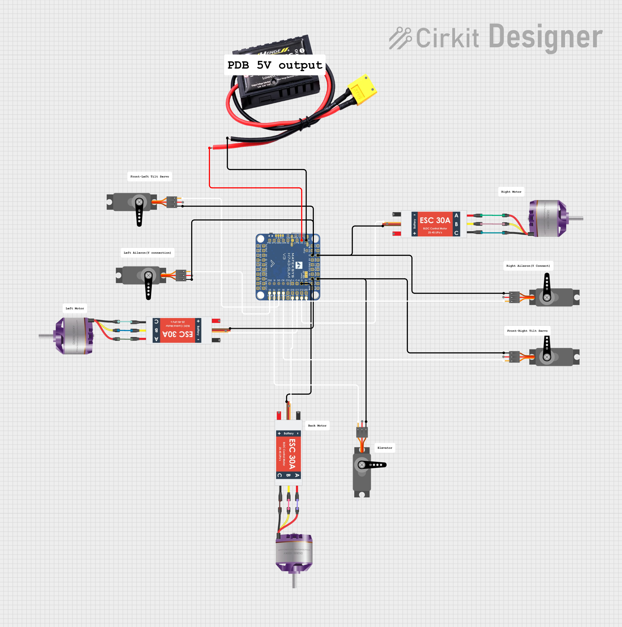
Usage Instructions
How to Use the H743 ESC in a Circuit
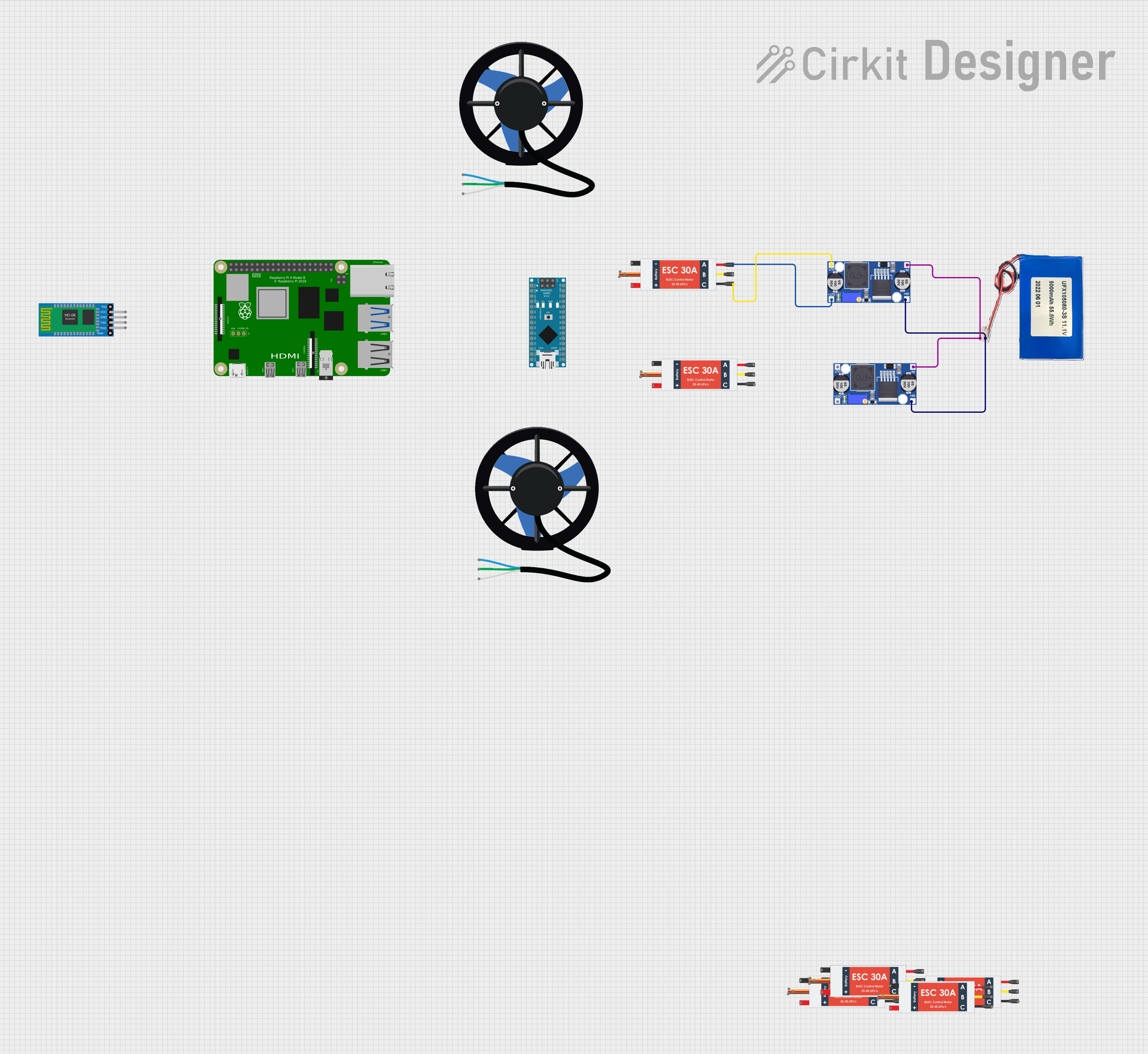
Connect the Power Supply:
- Attach the positive and negative terminals of the battery to the
Power Input (+)andPower Input (-)pins, respectively. - Ensure the battery voltage is within the supported range (2S–6S LiPo).
- Attach the positive and negative terminals of the battery to the
Connect the Motor:
- Connect the three motor wires to the
Motor Phase A,Motor Phase B, andMotor Phase Cpins. The order of connection determines the motor's rotation direction. Swap any two wires to reverse the direction.
- Connect the three motor wires to the
Connect the Signal Input:
- Connect the
Signal Inputpin to the PWM or digital signal output of your flight controller or receiver. - Connect the
Ground (GND)pin to the ground of the flight controller or receiver.
- Connect the
Configure the ESC:
- Use the programming card or software (if supported) to adjust settings such as throttle range, braking, and motor timing.
- Ensure the ESC is calibrated to match the throttle range of your transmitter.
Power On and Test:
- Power on the system and test the motor operation. Ensure the motor spins smoothly and responds correctly to throttle input.
Important Considerations
- Cooling: Ensure adequate airflow or cooling to prevent the ESC from overheating during operation.
- Wiring: Use appropriately rated wires and connectors to handle the current load.
- Signal Compatibility: Verify that the signal protocol (PWM, DShot, etc.) matches the output of your flight controller or receiver.
- Battery Selection: Use a battery with sufficient capacity and discharge rating to meet the motor's power requirements.
Example: Using the H743 ESC with an Arduino UNO
The following example demonstrates how to control the H743 ESC using an Arduino UNO and a PWM signal.
#include <Servo.h> // Include the Servo library for generating PWM signals

Servo esc; // Create a Servo object to control the ESC

void setup() {
  esc.attach(9); // Attach the ESC signal wire to pin 9 on the Arduino
  esc.writeMicroseconds(1000); // Send minimum throttle signal (1000 µs)
  delay(2000); // Wait for 2 seconds to allow the ESC to initialize
}

void loop() {
  esc.writeMicroseconds(1500); // Send mid-throttle signal (1500 µs)
  delay(5000); // Run the motor at mid-throttle for 5 seconds

  esc.writeMicroseconds(2000); // Send maximum throttle signal (2000 µs)
  delay(5000); // Run the motor at full throttle for 5 seconds

  esc.writeMicroseconds(1000); // Send minimum throttle signal (1000 µs)
  delay(5000); // Stop the motor for 5 seconds
}
Notes:
- Ensure the ESC is properly calibrated before running the code.
- Always test the setup with the motor securely mounted to avoid accidents.
Troubleshooting and FAQs
Common Issues and Solutions
Motor Does Not Spin:
- Verify all connections, especially the signal input and motor wires.
- Ensure the ESC is receiving a valid PWM or digital signal.
- Check the battery voltage and ensure it is within the supported range.
Motor Spins in the Wrong Direction:
- Swap any two of the three motor wires connected to the ESC.
ESC Overheats:
- Ensure proper cooling and avoid exceeding the continuous current rating.
- Check for loose or high-resistance connections.
No Response from ESC:
- Confirm that the ESC is powered on and receiving a valid signal.
- Recalibrate the throttle range using the transmitter or programming tool.
FAQs
Q: Can the H743 ESC be used with brushed motors?
A: No, the H743 ESC is designed specifically for brushless motors.
Q: How do I enable regenerative braking?
A: Regenerative braking can be enabled through the ESC's programming interface or software, if supported.
Q: What is the purpose of the BEC output?
A: The BEC (Battery Eliminator Circuit) provides regulated power to external devices, such as a receiver or flight controller, eliminating the need for a separate power source.
Q: Can I use the H743 ESC with a 7S LiPo battery?
A: No, the maximum supported input voltage is 6S (22.2V). Using a 7S battery may damage the ESC.
By following this documentation, users can effectively integrate the H743 ESC into their projects and troubleshoot common issues with ease.