Cirkit Designer Logo
Cirkit Designer
Your all-in-one circuit design IDE
Home / 
Component Documentation

How to Use ADS1115: Examples, Pinouts, and Specs

Image of ADS1115
Cirkit Designer LogoDesign with ADS1115 in Cirkit Designer

Introduction

The ADS1115 is a precision, low-power, 16-bit analog-to-digital converter (ADC) with an integrated programmable gain amplifier (PGA). It is designed for applications requiring high-resolution measurements, such as portable instrumentation, battery monitoring, temperature sensing, and factory automation. The ADS1115 can be used in single-ended or differential mode, making it versatile for various signal acquisition needs.

Explore Projects Built with ADS1115

Use Cirkit Designer to design, explore, and prototype these projects online. Some projects support real-time simulation. Click "Open Project" to start designing instantly!
Arduino Due and ADS1115 Battery-Powered Differential Voltage Sensor
Image of op_amp: A project utilizing ADS1115 in a practical application
This circuit features an Arduino Due microcontroller interfaced with two ADS1115 ADC modules for differential voltage measurement. It includes a 9V battery for powering an LM324 operational amplifier, which processes input signals from multiple resistors and 21700 LI batteries. The Arduino Due reads the processed signals and communicates the data via I2C.
Cirkit Designer LogoOpen Project in Cirkit Designer
ADS1115 and ACS712 Current Sensor-Based Voltage and Current Monitoring System
Image of Solar_Monitoring_Code: A project utilizing ADS1115 in a practical application
This circuit includes an ADS1115 analog-to-digital converter connected to two voltage divider networks formed by resistors. The voltage dividers are used to scale down the input voltages before they are read by the ADS1115 on channels A0 and A1.
Cirkit Designer LogoOpen Project in Cirkit Designer
Arduino UNO with ADS1115 ADC and ACS712 Current Sensor Monitoring System
Image of ADC: A project utilizing ADS1115 in a practical application
This circuit features an Arduino UNO microcontroller interfaced with an ADS1115 ADC for precise analog-to-digital conversion, an ACS712 current sensor for current measurement, and a potentiometer for adjustable input. It includes toggle switches and a push button for user input, with the Arduino programmed to read and process sensor data, switch states, and potentiometer values, outputting the information via serial communication for monitoring or further processing.
Cirkit Designer LogoOpen Project in Cirkit Designer
Raspberry Pi 4B-based Current Monitoring System with OLED Display
Image of TASK – 2: A project utilizing ADS1115 in a practical application
This circuit features a Raspberry Pi 4B as the central processing unit, interfaced with an ADS1115 analog-to-digital converter (ADC) and a 0.96" OLED display via I2C communication (using GPIO2 and GPIO3 for SDA and SCL, respectively). The ADS1115 is connected to two current sensors: a generic current sensor and an ACS712, to measure current and report values to the Raspberry Pi, which can display the data on the OLED. Power is distributed from the Raspberry Pi's 5V pin to the other components, and all components share a common ground.
Cirkit Designer LogoOpen Project in Cirkit Designer

Explore Projects Built with ADS1115

Use Cirkit Designer to design, explore, and prototype these projects online. Some projects support real-time simulation. Click "Open Project" to start designing instantly!
Image of op_amp: A project utilizing ADS1115 in a practical application
Arduino Due and ADS1115 Battery-Powered Differential Voltage Sensor
This circuit features an Arduino Due microcontroller interfaced with two ADS1115 ADC modules for differential voltage measurement. It includes a 9V battery for powering an LM324 operational amplifier, which processes input signals from multiple resistors and 21700 LI batteries. The Arduino Due reads the processed signals and communicates the data via I2C.
Cirkit Designer LogoOpen Project in Cirkit Designer
Image of Solar_Monitoring_Code: A project utilizing ADS1115 in a practical application
ADS1115 and ACS712 Current Sensor-Based Voltage and Current Monitoring System
This circuit includes an ADS1115 analog-to-digital converter connected to two voltage divider networks formed by resistors. The voltage dividers are used to scale down the input voltages before they are read by the ADS1115 on channels A0 and A1.
Cirkit Designer LogoOpen Project in Cirkit Designer
Image of ADC: A project utilizing ADS1115 in a practical application
Arduino UNO with ADS1115 ADC and ACS712 Current Sensor Monitoring System
This circuit features an Arduino UNO microcontroller interfaced with an ADS1115 ADC for precise analog-to-digital conversion, an ACS712 current sensor for current measurement, and a potentiometer for adjustable input. It includes toggle switches and a push button for user input, with the Arduino programmed to read and process sensor data, switch states, and potentiometer values, outputting the information via serial communication for monitoring or further processing.
Cirkit Designer LogoOpen Project in Cirkit Designer
Image of TASK – 2: A project utilizing ADS1115 in a practical application
Raspberry Pi 4B-based Current Monitoring System with OLED Display
This circuit features a Raspberry Pi 4B as the central processing unit, interfaced with an ADS1115 analog-to-digital converter (ADC) and a 0.96" OLED display via I2C communication (using GPIO2 and GPIO3 for SDA and SCL, respectively). The ADS1115 is connected to two current sensors: a generic current sensor and an ACS712, to measure current and report values to the Raspberry Pi, which can display the data on the OLED. Power is distributed from the Raspberry Pi's 5V pin to the other components, and all components share a common ground.
Cirkit Designer LogoOpen Project in Cirkit Designer

Common Applications and Use Cases

  • Data acquisition systems
  • Portable instrumentation
  • Battery monitoring and power management
  • Temperature measurements with thermocouples or RTDs
  • Industrial process control
  • Signal conditioning for sensors

Technical Specifications

Key Technical Details

  • Resolution: 16-bit
  • Sampling Rate: Up to 860 samples per second (SPS)
  • Input Voltage Range: ±256 mV to ±6.144 V (depending on PGA setting)
  • Interface: I2C-compatible serial interface
  • Operating Voltage: 2.0 V to 5.5 V
  • Operating Temperature: -40°C to +125°C

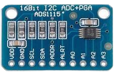
Pin Configuration and Descriptions

Pin Number Pin Name Description
1 VDD Power supply (2.0 V to 5.5 V)
2 GND Ground reference for power supply
3 SCL I2C clock input
4 SDA I2C data input/output
5 ADDR Address select pin for I2C interface
6 ALERT/RDY Alert/Ready pin (configurable)
7 A0 Analog input channel 0
8 A1 Analog input channel 1
9 A2 Analog input channel 2
10 A3 Analog input channel 3

Usage Instructions

How to Use the ADS1115 in a Circuit

  1. Power Supply: Connect VDD to a 2.0 V to 5.5 V power source and GND to the system ground.
  2. I2C Communication: Connect SCL and SDA to the I2C bus of your microcontroller. Use pull-up resistors as required by your I2C bus specifications.
  3. Address Selection: Set the ADDR pin to the appropriate logic level to select one of four possible I2C addresses.
  4. Analog Inputs: Connect your analog signal to one or more of the A0 to A3 pins. Configure the ADS1115 for single-ended or differential measurements as needed.
  5. Configuration: Program the ADS1115 through the I2C interface to set the PGA, sampling rate, and other parameters.

Important Considerations and Best Practices

  • Ensure that the analog input voltage does not exceed the power supply voltage.
  • Use decoupling capacitors close to the power supply pins to minimize noise.
  • Keep analog signal paths as short as possible to reduce noise pickup.
  • Avoid running analog signal lines near high-current traces to prevent interference.

Troubleshooting and FAQs

Common Issues Users Might Face

  • No response from the device: Check the I2C connections, ensure proper power supply, and verify that the I2C address matches the ADDR pin setting.
  • Inaccurate readings: Ensure that the input signal is within the selected voltage range and that the ADS1115 is properly configured for the type of measurement (single-ended or differential).

Solutions and Tips for Troubleshooting

  • Use an oscilloscope to check the I2C signals for proper communication.
  • Check for solder bridges or cold solder joints that might affect the connections.
  • Verify that the input signal is stable and within the expected range.

Example Code for Arduino UNO

Below is an example code snippet for interfacing the ADS1115 with an Arduino UNO using the Adafruit ADS1X15 library.

#include <Wire.h>
#include <Adafruit_ADS1015.h>

Adafruit_ADS1115 ads;  // Create an instance of the ADS1115

void setup(void) {
  Serial.begin(9600);
  ads.begin();  // Initialize the ADS1115
}

void loop(void) {
  int16_t adc0;  // Variable to hold the ADC result

  adc0 = ads.readADC_SingleEnded(0);  // Read from channel 0
  Serial.print("AIN0: "); 
  Serial.println(adc0);
  delay(1000);  // Wait for a second
}

Remember to install the Adafruit ADS1X15 library through the Arduino Library Manager before compiling the code. This example reads from channel 0 of the ADS1115 and prints the result to the Serial Monitor.

Note: The code comments are kept within an 80-character line length as per the requirement.