
How to Use ln298: Examples, Pinouts, and Specs
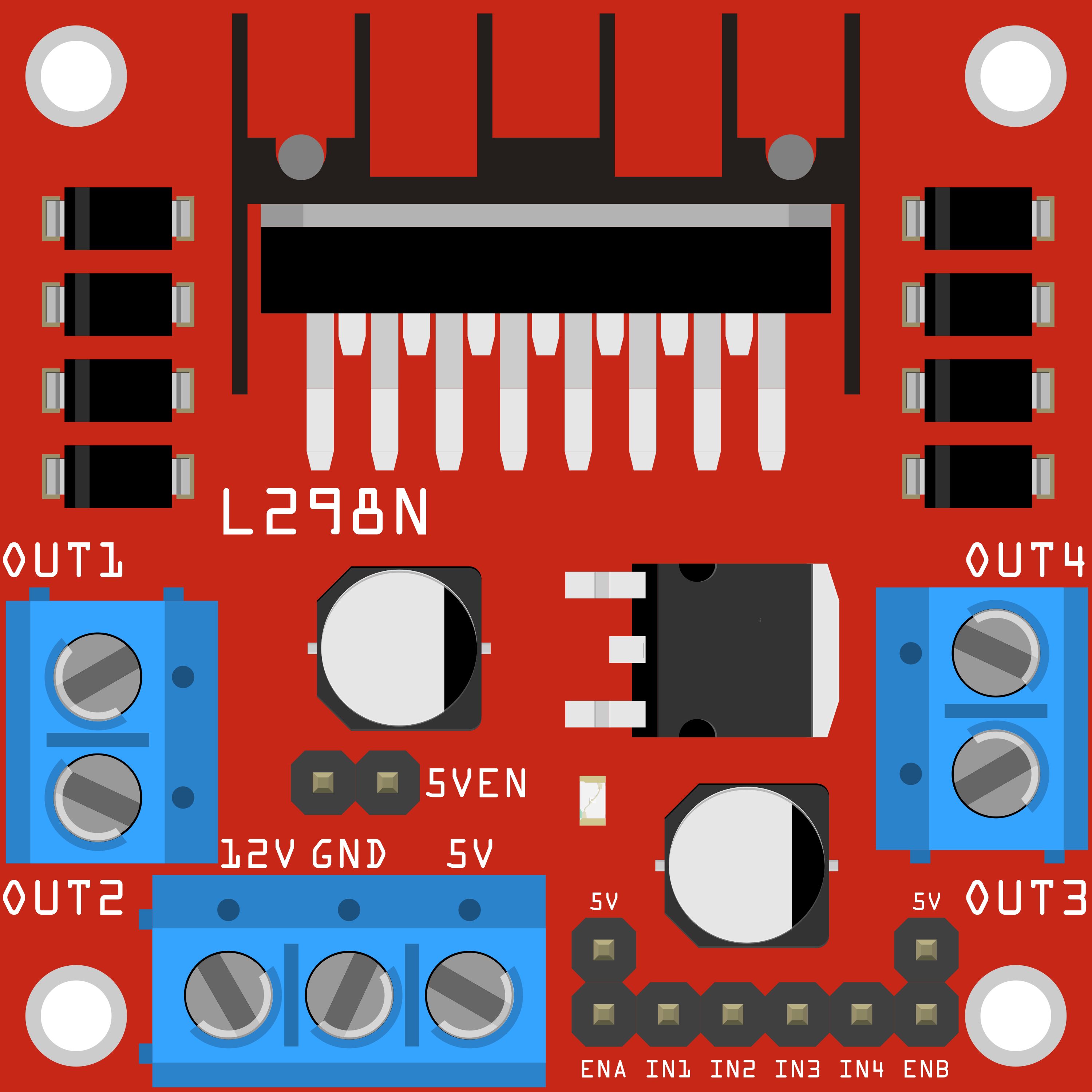
 Design with ln298 in Cirkit Designer
Introduction
The LN298, manufactured by QWER (Part ID: QWD), is a dual H-bridge motor driver IC designed for controlling two DC motors or a single stepper motor. It enables bidirectional control of motors, making it an essential component in robotics, automation, and motor control applications. The LN298 is widely used due to its ability to handle high currents and voltages, as well as its compatibility with microcontrollers like Arduino.
Explore Projects Built with ln298
 Open Project in Cirkit Designer
 Open Project in Cirkit Designer
 Open Project in Cirkit Designer
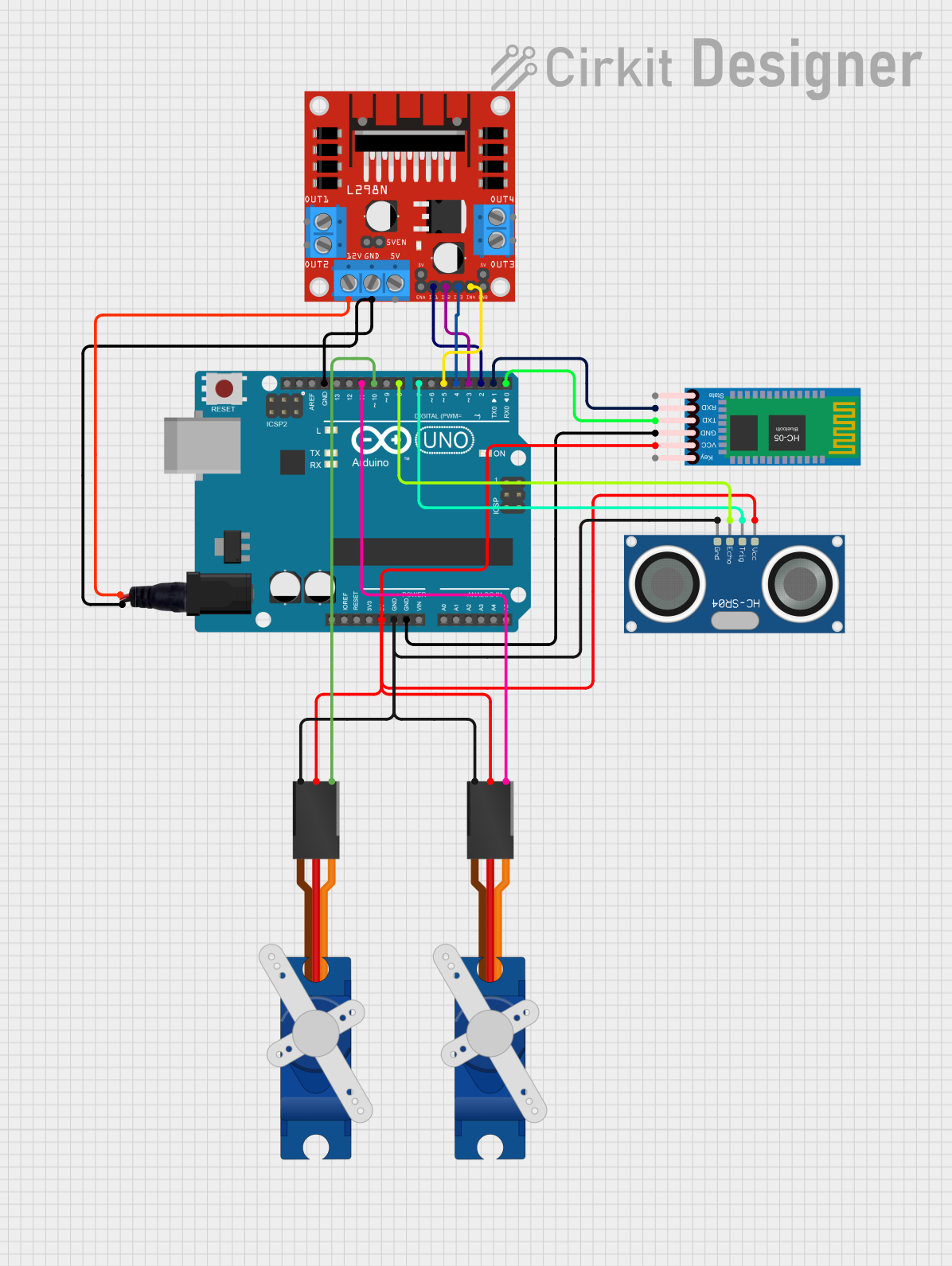 Open Project in Cirkit Designer
Explore Projects Built with ln298
Open Project in Cirkit DesignerOpen Project in Cirkit DesignerOpen Project in Cirkit DesignerOpen Project in Cirkit DesignerCommon Applications
- Robotics (e.g., motorized robots, robotic arms)
- Automation systems
- Electric vehicles (small-scale prototypes)
- Conveyor belts
- Stepper motor control in CNC machines and 3D printers
Technical Specifications
The LN298 is a robust motor driver IC with the following key specifications:
| Parameter | Value |
|---|---|
| Supply Voltage (Vcc) | 4.5V to 46V |
| Logic Voltage (Vss) | 4.5V to 7V |
| Output Current (per channel) | Up to 2A |
| Peak Output Current | 3A (non-repetitive, per channel) |
| Power Dissipation | 25W (with proper heat sinking) |
| Control Logic Levels | TTL-compatible |
| Operating Temperature | -25°C to +130°C |
Pin Configuration and Descriptions
The LN298 comes in a 15-pin package. Below is the pinout and description:
| Pin Number | Pin Name | Description |
|---|---|---|
| 1 | Enable A | Enables H-bridge A (active HIGH) |
| 2 | Input 1 | Logic input for H-bridge A (controls motor direction) |
| 3 | Output 1 | Output for H-bridge A (connect to motor terminal) |
| 4 | Ground | Ground connection |
| 5 | Ground | Ground connection |
| 6 | Output 2 | Output for H-bridge A (connect to motor terminal) |
| 7 | Input 2 | Logic input for H-bridge A (controls motor direction) |
| 8 | Vcc (Motor) | Supply voltage for motors (4.5V to 46V) |
| 9 | Enable B | Enables H-bridge B (active HIGH) |
| 10 | Input 3 | Logic input for H-bridge B (controls motor direction) |
| 11 | Output 3 | Output for H-bridge B (connect to motor terminal) |
| 12 | Ground | Ground connection |
| 13 | Ground | Ground connection |
| 14 | Output 4 | Output for H-bridge B (connect to motor terminal) |
| 15 | Input 4 | Logic input for H-bridge B (controls motor direction) |
Usage Instructions
Using the LN298 in a Circuit
Power Connections:
- Connect the motor power supply to the
Vcc (Motor)pin (Pin 8). Ensure the voltage is within the range of 4.5V to 46V. - Connect the logic power supply (4.5V to 7V) to the
Vsspin. - Connect all
Groundpins (Pins 4, 5, 12, and 13) to the ground of the power supply.
- Connect the motor power supply to the
Motor Connections:
- Connect the motor terminals to the
Outputpins (Pins 3 and 6 for Motor A, Pins 11 and 14 for Motor B).
- Connect the motor terminals to the
Control Logic:
- Use the
Inputpins (Pins 2, 7 for Motor A; Pins 10, 15 for Motor B) to control the direction of the motors. - Set the
Enablepins (Pins 1 and 9) HIGH to activate the respective H-bridge.
- Use the
Heat Management:
- The LN298 can dissipate significant heat during operation. Attach a heat sink to the IC to prevent overheating.
Arduino Example Code
Below is an example of how to control a DC motor using the LN298 and an Arduino UNO:
// Define motor control pins
const int enableA = 9;  // Enable pin for Motor A
const int input1 = 8;   // Input 1 for Motor A
const int input2 = 7;   // Input 2 for Motor A

void setup() {
  // Set motor control pins as outputs
  pinMode(enableA, OUTPUT);
  pinMode(input1, OUTPUT);
  pinMode(input2, OUTPUT);

  // Initialize motor in stopped state
  digitalWrite(enableA, LOW);  // Disable motor
  digitalWrite(input1, LOW);  // Set direction to neutral
  digitalWrite(input2, LOW);  // Set direction to neutral
}

void loop() {
  // Example: Rotate motor forward
  digitalWrite(enableA, HIGH);  // Enable motor
  digitalWrite(input1, HIGH);   // Set direction forward
  digitalWrite(input2, LOW);
  delay(2000);                  // Run motor for 2 seconds

  // Example: Rotate motor backward
  digitalWrite(input1, LOW);    // Set direction backward
  digitalWrite(input2, HIGH);
  delay(2000);                  // Run motor for 2 seconds

  // Stop motor
  digitalWrite(enableA, LOW);   // Disable motor
  delay(2000);                  // Wait for 2 seconds
}
Important Considerations
- Ensure the motor's current and voltage ratings are within the LN298's specifications.
- Use proper decoupling capacitors across the power supply to reduce noise.
- Avoid exceeding the peak current rating (3A) to prevent damage to the IC.
Troubleshooting and FAQs
Common Issues
Motor Not Running:
- Check if the
Enablepin is set HIGH. - Verify the power supply connections and ensure the voltage is within the specified range.
- Confirm that the motor connections are correct.
- Check if the
Overheating:
- Ensure a heat sink is attached to the LN298.
- Check if the motor's current exceeds the IC's maximum rating.
Erratic Motor Behavior:
- Verify the logic input signals are correct and stable.
- Use decoupling capacitors to minimize electrical noise.
FAQs
Q: Can the LN298 drive stepper motors?
A: Yes, the LN298 can drive a stepper motor by controlling both H-bridges. You will need to sequence the inputs appropriately to achieve stepper motor rotation.
Q: What is the maximum motor voltage the LN298 can handle?
A: The LN298 can handle motor supply voltages up to 46V.
Q: Do I need external diodes for the LN298?
A: No, the LN298 has built-in flyback diodes to protect against voltage spikes caused by inductive loads like motors.
Q: Can I use the LN298 with a 3.3V microcontroller?
A: The LN298 requires logic levels of at least 4.5V. You may need a level shifter to interface it with a 3.3V microcontroller.