Cirkit Designer Logo
Cirkit Designer
Your all-in-one circuit design IDE
Home / 
Component Documentation

How to Use AD8232 Gravity Sensor: Examples, Pinouts, and Specs

Image of AD8232 Gravity Sensor
Cirkit Designer LogoDesign with AD8232 Gravity Sensor in Cirkit Designer

Introduction

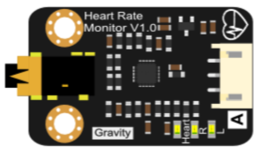
The AD8232 Gravity Sensor by DFRobot is a specialized bio-potential signal acquisition device tailored for electrocardiogram (ECG) and electromyography (EMG) applications. It is designed to measure the electrical activity of the heart and muscles by amplifying and filtering the bio-potential signals. This sensor is commonly used in wearable health monitoring devices, fitness trackers, and medical diagnostic equipment.

Explore Projects Built with AD8232 Gravity Sensor

Use Cirkit Designer to design, explore, and prototype these projects online. Some projects support real-time simulation. Click "Open Project" to start designing instantly!
Heltec LoRa V2 and AD8232 Gravity Sensor-Based Health Monitoring System with GPS
Image of heart rate with Lora module: A project utilizing AD8232 Gravity Sensor in a practical application
This circuit integrates a Heltec LoRa V2 microcontroller with an AD8232 Gravity Sensor to read and transmit analog heart rate data. The sensor's output is connected to the microcontroller, which reads the data and prints it to the Serial Monitor. The circuit is designed for remote health monitoring applications.
Cirkit Designer LogoOpen Project in Cirkit Designer
Triple AD8232 Heart Rate Monitor with Arduino Uno
Image of DfRobot_Arduino: A project utilizing AD8232 Gravity Sensor in a practical application
This circuit is designed to monitor heart rate signals using three AD8232 Gravity Heart Rate Sensors connected to an Arduino Uno R3. The sensors' analog outputs are connected to the Arduino's analog input pins A0, A1, and A2 for signal processing. The common ground and power supply connections indicate that all sensors are powered by the Arduino, which likely processes and interprets the heart rate signals from multiple channels.
Cirkit Designer LogoOpen Project in Cirkit Designer
Arduino Nano-Based Health Monitoring System with Wi-Fi and GPS
Image of zekooo: A project utilizing AD8232 Gravity Sensor in a practical application
This circuit is a sensor-based data acquisition system using an Arduino Nano, which collects data from a GSR sensor, an ADXL377 accelerometer, and a Neo 6M GPS module. The collected data is then transmitted via a WiFi module (ESP8266-01) for remote monitoring. The system is powered by a 12V battery, which is charged by a solar panel.
Cirkit Designer LogoOpen Project in Cirkit Designer
Wi-Fi Enabled Sensor Hub with ESP8266 and ADS1115 ADC
Image of Node Mcu Gas Sensor: A project utilizing AD8232 Gravity Sensor in a practical application
This circuit features two ESP8266 NodeMCU microcontrollers, each interfaced with a Gravity I2C ADS1115 16-Bit ADC module for analog-to-digital conversion. The microcontrollers communicate with the ADC modules via I2C protocol, with one set of connections for each microcontroller-ADC pair, and are powered through a common 3.3V and ground connection.
Cirkit Designer LogoOpen Project in Cirkit Designer

Explore Projects Built with AD8232 Gravity Sensor

Use Cirkit Designer to design, explore, and prototype these projects online. Some projects support real-time simulation. Click "Open Project" to start designing instantly!
Image of heart rate with Lora module: A project utilizing AD8232 Gravity Sensor in a practical application
Heltec LoRa V2 and AD8232 Gravity Sensor-Based Health Monitoring System with GPS
This circuit integrates a Heltec LoRa V2 microcontroller with an AD8232 Gravity Sensor to read and transmit analog heart rate data. The sensor's output is connected to the microcontroller, which reads the data and prints it to the Serial Monitor. The circuit is designed for remote health monitoring applications.
Cirkit Designer LogoOpen Project in Cirkit Designer
Image of DfRobot_Arduino: A project utilizing AD8232 Gravity Sensor in a practical application
Triple AD8232 Heart Rate Monitor with Arduino Uno
This circuit is designed to monitor heart rate signals using three AD8232 Gravity Heart Rate Sensors connected to an Arduino Uno R3. The sensors' analog outputs are connected to the Arduino's analog input pins A0, A1, and A2 for signal processing. The common ground and power supply connections indicate that all sensors are powered by the Arduino, which likely processes and interprets the heart rate signals from multiple channels.
Cirkit Designer LogoOpen Project in Cirkit Designer
Image of zekooo: A project utilizing AD8232 Gravity Sensor in a practical application
Arduino Nano-Based Health Monitoring System with Wi-Fi and GPS
This circuit is a sensor-based data acquisition system using an Arduino Nano, which collects data from a GSR sensor, an ADXL377 accelerometer, and a Neo 6M GPS module. The collected data is then transmitted via a WiFi module (ESP8266-01) for remote monitoring. The system is powered by a 12V battery, which is charged by a solar panel.
Cirkit Designer LogoOpen Project in Cirkit Designer
Image of Node Mcu Gas Sensor: A project utilizing AD8232 Gravity Sensor in a practical application
Wi-Fi Enabled Sensor Hub with ESP8266 and ADS1115 ADC
This circuit features two ESP8266 NodeMCU microcontrollers, each interfaced with a Gravity I2C ADS1115 16-Bit ADC module for analog-to-digital conversion. The microcontrollers communicate with the ADC modules via I2C protocol, with one set of connections for each microcontroller-ADC pair, and are powered through a common 3.3V and ground connection.
Cirkit Designer LogoOpen Project in Cirkit Designer

Common Applications and Use Cases

  • Personal and clinical ECG monitoring
  • Heart rate monitoring for fitness applications
  • Biomedical research
  • Educational purposes for learning about bio-potential signals

Technical Specifications

Key Technical Details

  • Operating Voltage: 3.3V to 6V
  • Output Type: Analog
  • Gain: Adjustable with onboard potentiometer
  • Common Mode Rejection Ratio (CMRR): >80dB
  • Bandwidth (Filter Range): 0.05Hz to 40Hz

Pin Configuration and Descriptions

Pin Number Pin Name Description
1 GND Ground
2 3.3V Power supply (3.3V)
3 OUTPUT Analog ECG output signal
4 LO+ Lead-off detection positive
5 LO- Lead-off detection negative
6 SDN Shutdown pin (active low)

Usage Instructions

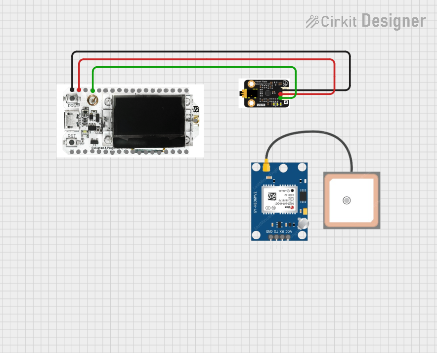
How to Use the Component in a Circuit

  1. Connect the GND pin to the ground of your power supply.
  2. Connect the 3.3V pin to a 3.3V power supply.
  3. Connect the OUTPUT pin to an analog input on your microcontroller (e.g., Arduino UNO).
  4. Attach LO+ and LO- to the body using biopotential electrodes.
  5. Optionally, connect the SDN pin to a digital output on your microcontroller to control the power state of the sensor.

Important Considerations and Best Practices

  • Ensure that the skin where electrodes are placed is clean and dry to improve signal quality.
  • Avoid placing electrodes close to muscles to reduce EMG interference unless EMG measurement is desired.
  • Use shielded cables for electrode connections to minimize noise.
  • Do not use the sensor for medical diagnostics without proper certification and testing.

Example Code for Arduino UNO

// AD8232 Heart Rate Monitor
const int OUTPUT_PIN = A0; // Analog output from the AD8232
const int LO_PLUS_PIN = 10; // LO+ pin of the AD8232
const int LO_MINUS_PIN = 11; // LO- pin of the AD8232

void setup() {
  Serial.begin(9600);
  pinMode(LO_PLUS_PIN, INPUT); // Setup for lead off detection
  pinMode(LO_MINUS_PIN, INPUT); // Setup for lead off detection
}

void loop() {
  if((digitalRead(LO_PLUS_PIN) == 1)||(digitalRead(LO_MINUS_PIN) == 1)){
    Serial.println("Lead off detected");
  }
  else{
    int ecgValue = analogRead(OUTPUT_PIN);
    Serial.println(ecgValue);
  }
  delay(200); // Delay for stability
}

Troubleshooting and FAQs

Common Issues Users Might Face

  • Noisy Signal: Ensure that the sensor is properly connected, and the skin is clean where the electrodes are attached. Also, check for loose connections.
  • Flat Line Output: This could indicate that the electrodes are not properly attached or the subject is not connected.
  • Intermittent Signal Loss: Check if the lead-off detection (LO+ and LO-) indicates that the leads have come off.

Solutions and Tips for Troubleshooting

  • If the signal is noisy, try repositioning the electrodes or using a different body location.
  • Ensure that the power supply is stable and falls within the specified voltage range.
  • For flat line output, reattach the electrodes and ensure they have good contact with the skin.

FAQs

Q: Can the AD8232 be used for medical purposes? A: While the AD8232 can be used for educational and hobbyist projects, it is not certified for medical use without proper testing and certification.

Q: How can I improve the quality of the ECG signal? A: Use high-quality electrodes, ensure stable power supply, and keep the sensor and cables away from noise sources such as power lines and mobile phones.

Q: What should I do if the sensor is not working? A: Check all connections, ensure the power supply is within the specified range, and verify that the electrodes are properly attached to the subject.