How to Use BH-01-E Speed Controller: Examples, Pinouts, and Specs
Introduction
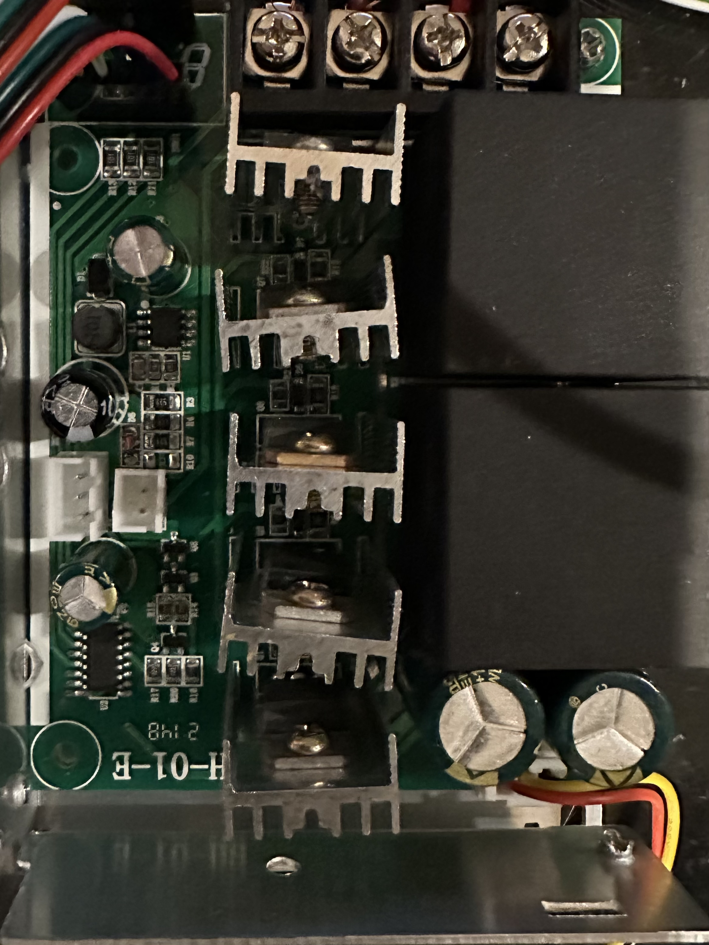
The BH-01-E Speed Controller, manufactured in China, is a versatile and reliable electronic component designed for controlling the speed and direction of electric motors. It is widely used in robotics, automation systems, and other applications requiring precise motor control. This controller is compatible with a variety of DC motors and provides smooth, efficient operation, making it an essential component for hobbyists and professionals alike.
Explore Projects Built with BH-01-E Speed Controller
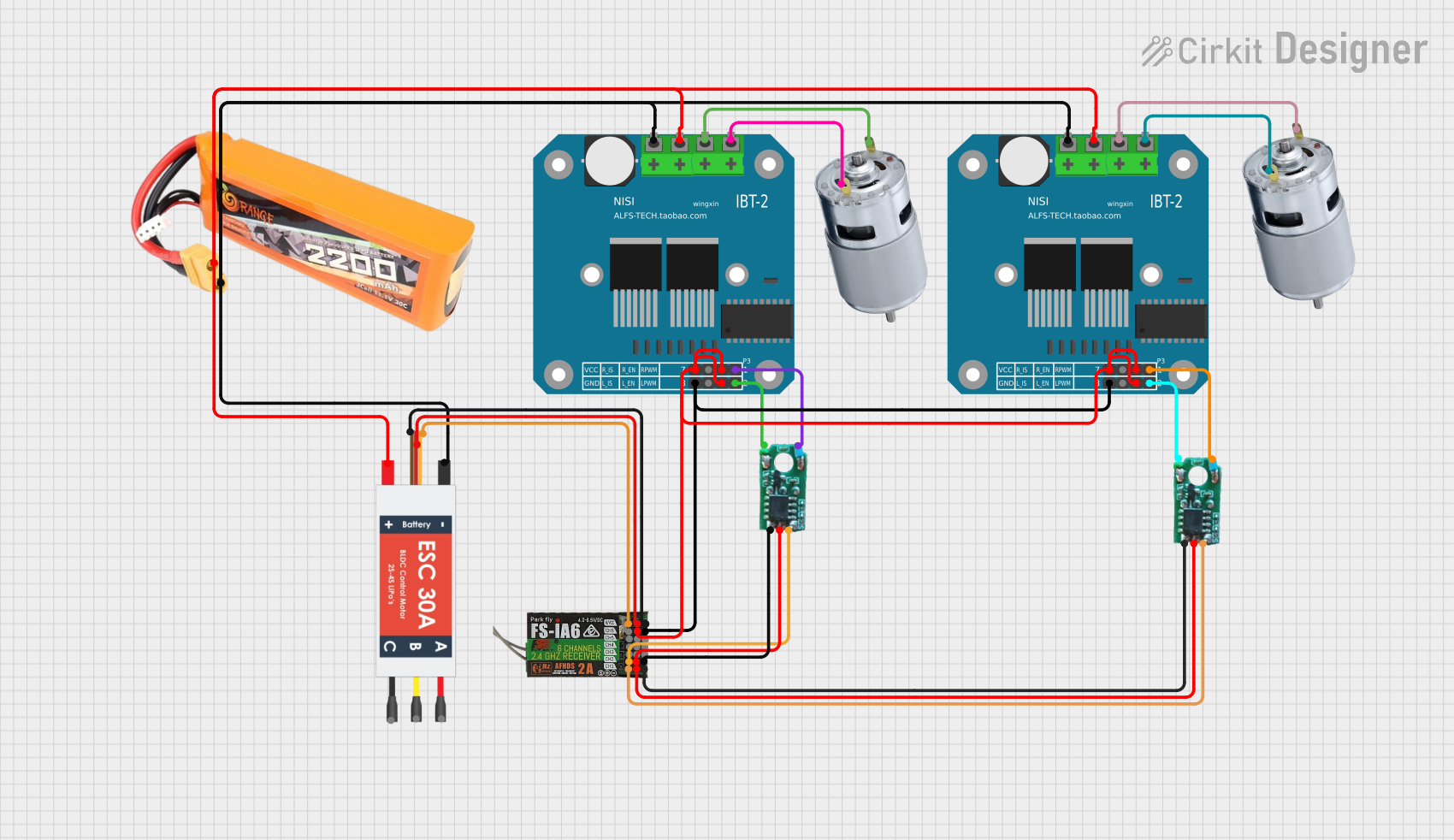
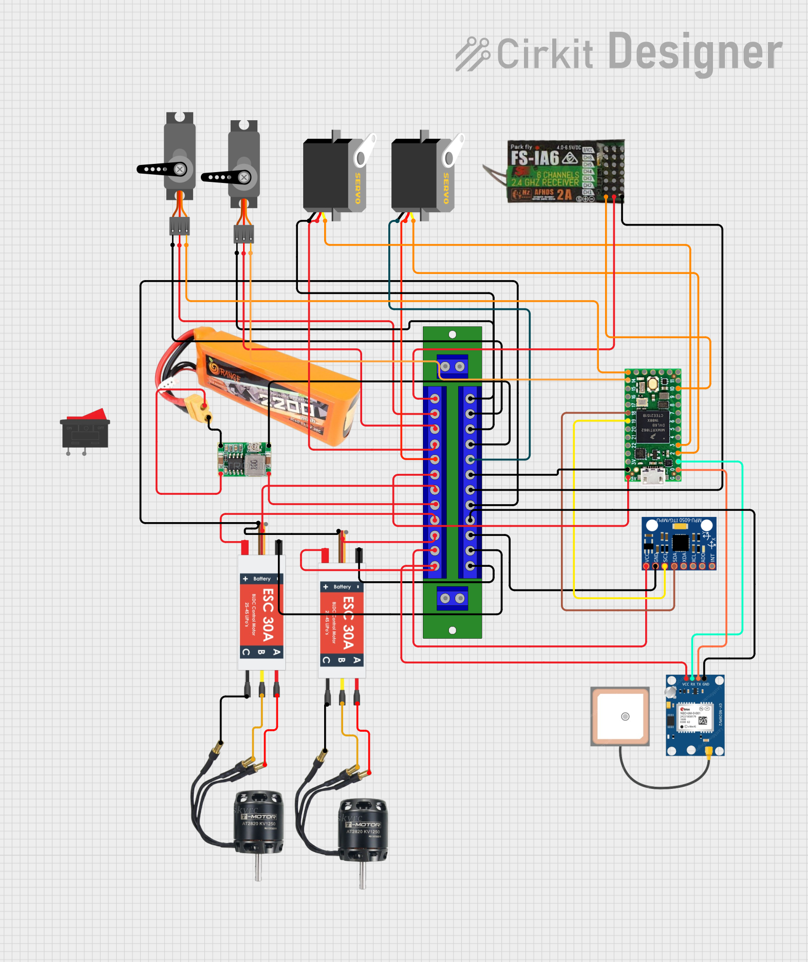

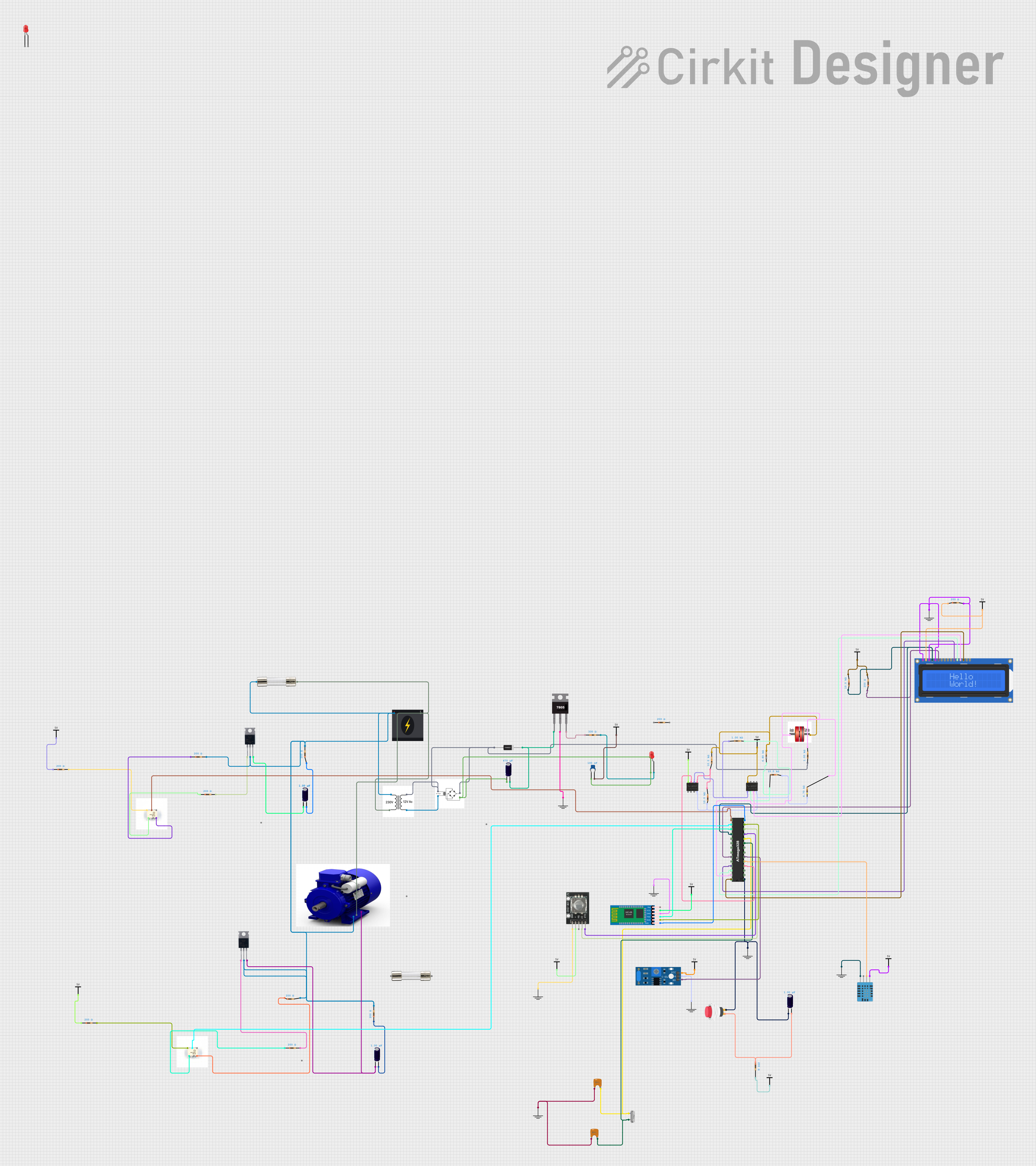
Explore Projects Built with BH-01-E Speed Controller
Common Applications
- Robotics: Controlling motor speed for robotic arms, wheels, and actuators.
- Automation: Managing conveyor belts, fans, and other motorized systems.
- Electric vehicles: Regulating motor speed for small electric vehicles or carts.
- DIY projects: Ideal for hobbyists building motorized systems.
Technical Specifications
The BH-01-E Speed Controller is designed to handle a range of motor control requirements. Below are its key technical details:
General Specifications
| Parameter | Value |
|---|---|
| Input Voltage Range | 6V to 24V DC |
| Maximum Current | 10A |
| Control Signal Type | PWM (Pulse Width Modulation) |
| PWM Frequency | 1 kHz to 20 kHz |
| Motor Compatibility | Brushed DC motors |
| Operating Temperature | -10°C to 50°C |
| Dimensions | 50mm x 30mm x 15mm |
| Weight | 25g |
Pin Configuration
The BH-01-E Speed Controller features a simple pin layout for easy integration into circuits. Below is the pin configuration:
| Pin Number | Label | Description |
|---|---|---|
| 1 | VIN (+) | Positive input voltage (6V to 24V DC). |
| 2 | GND (-) | Ground connection for the power supply. |
| 3 | M+ | Positive terminal for the motor connection. |
| 4 | M- | Negative terminal for the motor connection. |
| 5 | PWM | PWM input signal for speed control. |
| 6 | DIR | Direction control input (HIGH/LOW for direction). |
Usage Instructions
The BH-01-E Speed Controller is straightforward to use in a circuit. Follow the steps below to integrate and operate the controller:
Connecting the BH-01-E
- Power Supply: Connect the positive terminal of your DC power supply to the
VIN (+)pin and the negative terminal to theGND (-)pin. - Motor Connection: Attach the motor's positive terminal to the
M+pin and the negative terminal to theM-pin. - Control Signals:
- Connect a PWM signal (e.g., from a microcontroller) to the
PWMpin to control motor speed. - Use the
DIRpin to set the motor's direction:HIGH(logic 1): Forward direction.LOW(logic 0): Reverse direction.
- Connect a PWM signal (e.g., from a microcontroller) to the
Important Considerations
- Ensure the input voltage matches the motor's operating voltage to avoid damage.
- Use a heat sink or cooling system if operating at high currents for extended periods.
- Verify the PWM frequency is within the supported range (1 kHz to 20 kHz).
- Avoid reversing the power supply polarity, as this may damage the controller.
Example: Using BH-01-E with Arduino UNO
Below is an example of how to control the BH-01-E Speed Controller using an Arduino UNO:
// Example code to control the BH-01-E Speed Controller with Arduino UNO

// Define pin connections
const int pwmPin = 9;  // PWM signal connected to pin 9
const int dirPin = 8;  // Direction control connected to pin 8

void setup() {
  // Set pin modes
  pinMode(pwmPin, OUTPUT);
  pinMode(dirPin, OUTPUT);

  // Initialize motor direction to forward
  digitalWrite(dirPin, HIGH);
}

void loop() {
  // Gradually increase motor speed
  for (int speed = 0; speed <= 255; speed++) {
    analogWrite(pwmPin, speed); // Set PWM duty cycle (0-255)
    delay(20);                  // Wait 20ms before increasing speed
  }

  // Gradually decrease motor speed
  for (int speed = 255; speed >= 0; speed--) {
    analogWrite(pwmPin, speed); // Set PWM duty cycle (0-255)
    delay(20);                  // Wait 20ms before decreasing speed
  }

  // Reverse motor direction
  digitalWrite(dirPin, LOW);    // Set direction to reverse
  delay(1000);                  // Wait 1 second before repeating
}
Notes:
- The
analogWrite()function generates a PWM signal on the specified pin. - Adjust the delay values to control the acceleration and deceleration rates.
Troubleshooting and FAQs
Common Issues
Motor not spinning:
- Check the power supply voltage and ensure it matches the motor's requirements.
- Verify all connections, especially the motor and power supply terminals.
- Ensure the PWM signal is being generated correctly.
Motor spins in the wrong direction:
- Reverse the logic level on the
DIRpin (HIGH to LOW or vice versa). - Alternatively, swap the motor connections on the
M+andM-pins.
- Reverse the logic level on the
Controller overheating:
- Ensure the current draw does not exceed 10A.
- Use a heat sink or cooling fan if operating at high currents.
PWM signal not working:
- Confirm the PWM frequency is within the supported range (1 kHz to 20 kHz).
- Check the microcontroller's PWM pin configuration.
FAQs
Q: Can the BH-01-E control brushless motors?
A: No, the BH-01-E is designed specifically for brushed DC motors.
Q: What happens if I exceed the maximum current rating?
A: Exceeding the 10A limit may damage the controller. Use a fuse or current limiter for protection.
Q: Can I use the BH-01-E with a 3.3V microcontroller?
A: Yes, but ensure the PWM and DIR pins are compatible with 3.3V logic levels. If not, use a level shifter.
Q: Is reverse polarity protection included?
A: No, the BH-01-E does not have built-in reverse polarity protection. Double-check connections before powering the circuit.