How to Use V_REG_NCP50X: Examples, Pinouts, and Specs
Introduction
The V_REG_NCP50X is a series of low dropout (LDO) voltage regulators designed to deliver a stable and precise output voltage with low power dissipation. These components are particularly suitable for battery-powered devices, portable electronics, and any application where voltage regulation is critical for performance and energy efficiency. The V_REG_NCP50X series is appreciated for its ease of use, reliability, and compact form factor.
Explore Projects Built with V_REG_NCP50X
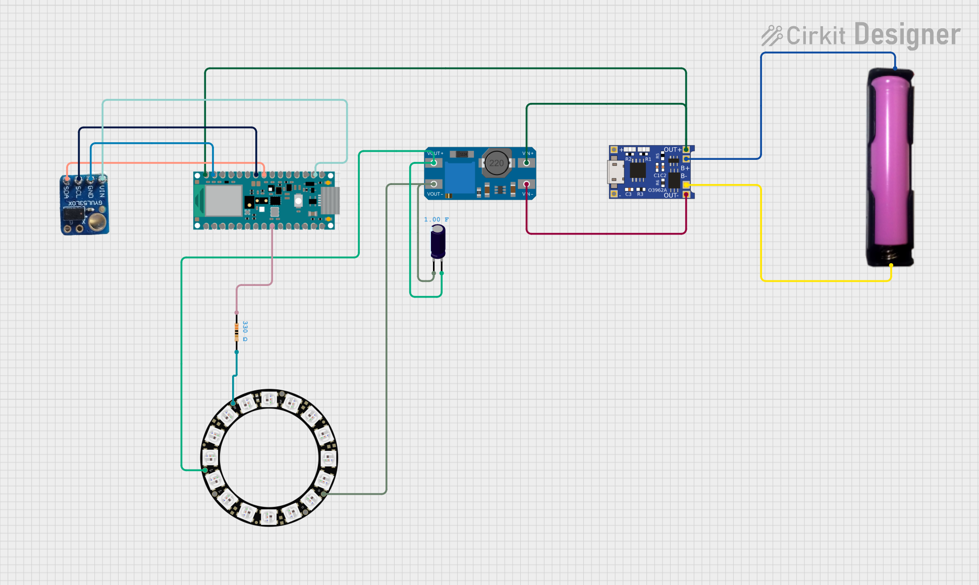
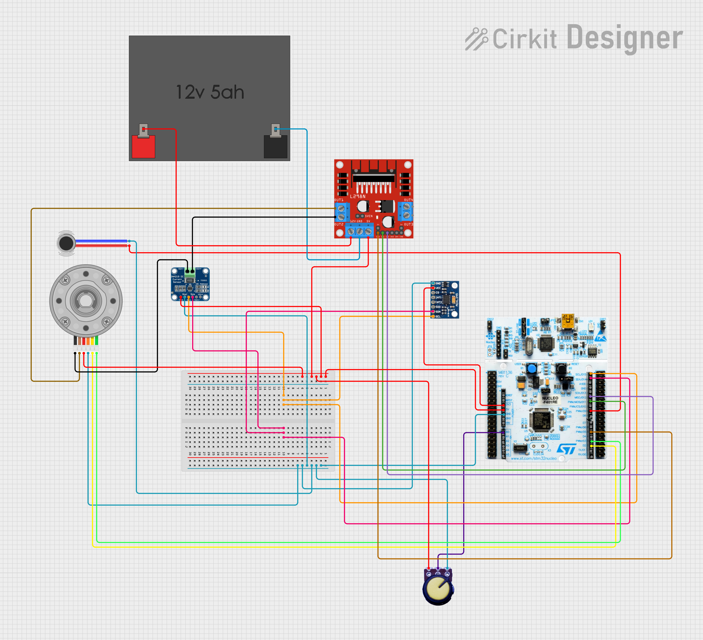
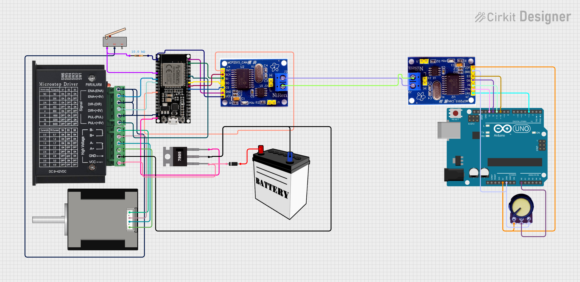

Explore Projects Built with V_REG_NCP50X
Common Applications and Use Cases
- Battery-powered devices
- Portable electronics
- Microcontroller power supply
- Power management for IoT devices
- Automotive electronics
Technical Specifications
The V_REG_NCP50X series offers a variety of fixed output voltages. Below are the key technical details for a generic V_REG_NCP50X component. Replace the values with the specific model's parameters you are using.
| Parameter | Value | Description |
|---|---|---|
| Output Voltage (V) | 3.3V / 5V / ... | Fixed output voltage provided by the LDO. |
| Input Voltage (Vin) | 2.7V to 5.5V | Operating input voltage range. |
| Output Current (I) | Up to 150mA | Maximum current the LDO can provide. |
| Dropout Voltage | 0.12V at 50mA | Voltage drop between input and output at a specified load current. |
| Quiescent Current | 20µA | Current consumed by the LDO when no load is connected. |
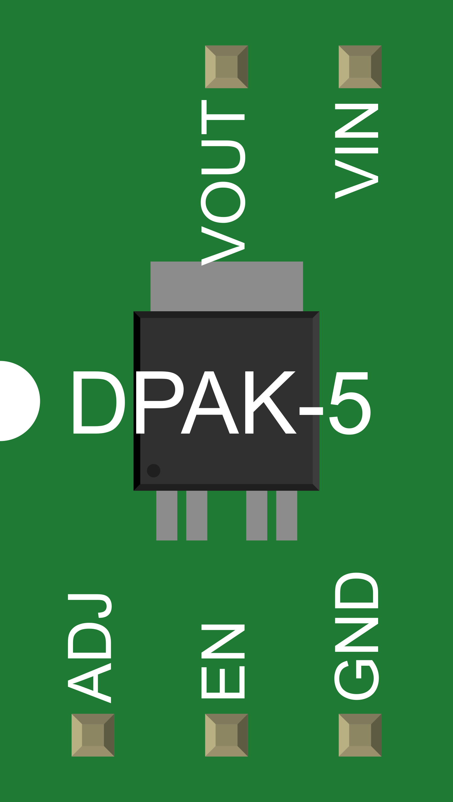
| Package | SOT-23-5 | Physical packaging and pin configuration. |
Pin Configuration and Descriptions
| Pin Number | Name | Description |
|---|---|---|
| 1 | Vin | Input voltage. Connect to the power source. |
| 2 | GND | Ground. Connect to the system ground. |
| 3 | NC | No Connection. Leave this pin unconnected. |
| 4 | Vout | Regulated output voltage. Connect to the load. |
| 5 | EN | Enable pin. Drive high to enable the LDO. |
Usage Instructions
How to Use the Component in a Circuit
- Connect the Vin pin to your power source, ensuring it falls within the specified input voltage range.
- Attach the GND pin to the common ground of your circuit.
- Leave the NC (No Connection) pin unconnected.
- Connect the Vout pin to the power input of your device or circuit that requires regulated voltage.
- The EN (Enable) pin can be tied directly to Vin if always-on operation is desired. Alternatively, it can be controlled by a microcontroller or switch to enable or disable the regulator as needed.
Important Considerations and Best Practices
- Always ensure that the input voltage does not exceed the maximum rating to prevent damage.
- Place a capacitor (typically 1µF to 10µF) close to the Vin and Vout pins to stabilize the input and output respectively and filter out noise.
- Avoid applying a load that draws more current than the maximum output current rating.
- Use appropriate heat sinking if the power dissipation is expected to be high due to a large voltage drop and high load current.
- Ensure the EN pin is not left floating to prevent erratic behavior.
Troubleshooting and FAQs
Common Issues Users Might Face
- Output voltage is lower than expected: Check if the input voltage is within the specified range and if the load current is not exceeding the maximum rating.
- Regulator is overheating: Ensure that the power dissipation is within the limits by checking the input voltage and load current. Add a heat sink if necessary.
- No output voltage: Verify that the EN pin is properly driven high and that the input voltage is present and within the specified range.
Solutions and Tips for Troubleshooting
- If the output voltage is unstable, check the capacitors at the Vin and Vout pins for proper value and placement.
- In case of overheating, reduce the load current or improve heat dissipation.
- If there is no output, ensure that the EN pin is correctly configured and that the input voltage is applied.
FAQs
Q: Can I use the V_REG_NCP50X without an external capacitor? A: It is strongly recommended to use external capacitors for stability and noise reduction.
Q: What happens if the EN pin is left unconnected? A: The EN pin should not be left floating as it may lead to unpredictable behavior. Tie it to Vin or control it with a logic signal.
Q: Is the V_REG_NCP50X series suitable for automotive applications? A: Yes, but ensure that the specific model meets the automotive industry's standards and the operating conditions of your application.
Example Connection with Arduino UNO
The following example demonstrates how to connect the V_REG_NCP50X to an Arduino UNO to provide a regulated power supply for the microcontroller.
// No specific code is required for the V_REG_NCP50X as it is a hardware component.
// However, the following is an example of how to set up the enable pin.

const int enablePin = 2; // Connect the EN pin of V_REG_NCP50X to digital pin 2

void setup() {
  pinMode(enablePin, OUTPUT); // Set the enable pin as an output
  digitalWrite(enablePin, HIGH); // Enable the voltage regulator
}

void loop() {
  // Your code here
}
Remember to comment the code appropriately, keeping the line length within 80 characters for readability.