Cirkit Designer
Your all-in-one circuit design IDE
Home /
Component Documentation
How to Use 1.28" Round LCD, ESP32-S3 Board: Examples, Pinouts, and Specs
Introduction
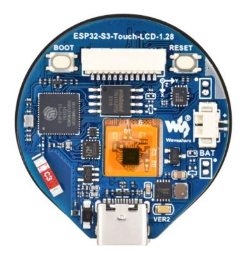
The 1.28" Round LCD, ESP32-S3 Board by Waveshare is a compact and versatile development board that integrates an ESP32-S3 microcontroller with a 1.28-inch round LCD display. This board is designed for IoT applications, wearable devices, and projects requiring a visually appealing display. The ESP32-S3 microcontroller provides dual-core processing power, Wi-Fi, and Bluetooth connectivity, making it ideal for a wide range of applications.
Explore Projects Built with 1.28" Round LCD, ESP32-S3 Board
ESP32-Powered 1.3 inch TFT Display Module for Visual Data Output

This circuit connects an ESP32 microcontroller to a 1.3 inch TFT display module (ST7789). The ESP32 provides power and control signals to the display, enabling it to show graphical data.
ESP32-S3 and ILI9488 TFT LCD Display for Interactive Graphics
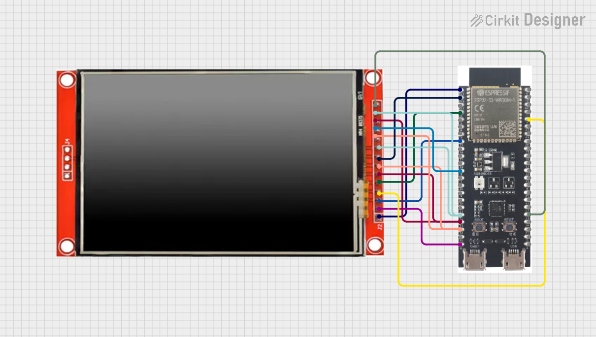
This circuit features an ESP32-S3 microcontroller connected to an ILI9488 TFT LCD display. The ESP32-S3 initializes and controls the display, demonstrating basic graphics and text rendering using the TFT_eSPI library.
ESP32-S3 Powered Tri-Color E-Ink Display Demo

This circuit integrates an ESP32-S3 microcontroller with a 2.9" Tri-Color E-Ink display, enabling the microcontroller to control the display for rendering graphics and text. The ESP32-S3 communicates with the display using SPI protocol, allowing for dynamic visual output such as animations and text updates in red, black, and white.
ESP32-Based OLED Display Interface

This circuit features an ESP32 microcontroller connected to an OLED 1.3" display. The ESP32's GPIO pins 21 and 22 are used for I2C communication (SDA and SCL respectively) with the OLED display. The display is powered by the 5V output from the ESP32, and both devices share a common ground.
Explore Projects Built with 1.28" Round LCD, ESP32-S3 Board
ESP32-Powered 1.3 inch TFT Display Module for Visual Data Output
This circuit connects an ESP32 microcontroller to a 1.3 inch TFT display module (ST7789). The ESP32 provides power and control signals to the display, enabling it to show graphical data.
ESP32-S3 and ILI9488 TFT LCD Display for Interactive Graphics
This circuit features an ESP32-S3 microcontroller connected to an ILI9488 TFT LCD display. The ESP32-S3 initializes and controls the display, demonstrating basic graphics and text rendering using the TFT_eSPI library.
ESP32-S3 Powered Tri-Color E-Ink Display Demo
This circuit integrates an ESP32-S3 microcontroller with a 2.9" Tri-Color E-Ink display, enabling the microcontroller to control the display for rendering graphics and text. The ESP32-S3 communicates with the display using SPI protocol, allowing for dynamic visual output such as animations and text updates in red, black, and white.
ESP32-Based OLED Display Interface
This circuit features an ESP32 microcontroller connected to an OLED 1.3" display. The ESP32's GPIO pins 21 and 22 are used for I2C communication (SDA and SCL respectively) with the OLED display. The display is powered by the 5V output from the ESP32, and both devices share a common ground.
Common Applications and Use Cases
- Wearable devices (e.g., smartwatches, fitness trackers)
- IoT projects with graphical interfaces
- Home automation systems
- Portable monitoring devices
- Educational and prototyping projects
Technical Specifications
Key Technical Details
| Parameter | Specification |
|---|---|
| Microcontroller | ESP32-S3 |
| Display Type | 1.28" round LCD, 240x240 resolution |
| Communication Interface | SPI |
| Connectivity | Wi-Fi 802.11 b/g/n, Bluetooth 5.0 |
| Operating Voltage | 3.3V |
| Power Supply | USB Type-C or external 3.3V source |
| Flash Memory | 16MB |
| PSRAM | 8MB |
| Dimensions | 54mm x 54mm |
Pin Configuration and Descriptions
| Pin Name | Pin Number | Description |
|---|---|---|
| 3V3 | 1 | 3.3V power input |
| GND | 2 | Ground |
| IO18 | 3 | SPI Clock (SCK) |
| IO19 | 4 | SPI Data Out (MOSI) |
| IO21 | 5 | SPI Data In (MISO) |
| IO22 | 6 | SPI Chip Select (CS) |
| IO23 | 7 | LCD Data/Command (DC) |
| IO25 | 8 | LCD Reset (RST) |
| IO26 | 9 | Backlight Control (BL) |
| IO27 | 10 | Touch Panel Interrupt (if applicable) |
Usage Instructions
How to Use the Component in a Circuit
- Power the Board: Connect the 3.3V pin to a 3.3V power source or use the USB Type-C port for power.
- Connect SPI Interface: Use the SPI pins (SCK, MOSI, MISO, CS) to interface with the LCD display.
- Control the LCD: Use the DC, RST, and BL pins to manage the display's data/command mode, reset, and backlight.
- Program the ESP32-S3: Use the USB Type-C port to upload code to the ESP32-S3 microcontroller.
Important Considerations and Best Practices
- Ensure the power supply provides a stable 3.3V to avoid damaging the board.
- Use appropriate pull-up or pull-down resistors for unused GPIO pins to prevent floating states.
- When using the LCD, ensure the SPI clock frequency does not exceed the display's maximum supported frequency.
- Avoid exposing the board to static electricity or moisture to prevent damage.
Example Code for Arduino UNO
Below is an example of how to interface the 1.28" Round LCD with the ESP32-S3 using the Arduino IDE:
#include <SPI.h>
#include <TFT_eSPI.h> // Include the TFT library for the LCD

// Define pins for the LCD
#define TFT_CS   22  // Chip Select pin
#define TFT_DC   23  // Data/Command pin
#define TFT_RST  25  // Reset pin
#define TFT_BL   26  // Backlight pin

// Initialize the TFT display
TFT_eSPI tft = TFT_eSPI();

void setup() {
  // Initialize serial communication for debugging
  Serial.begin(115200);

  // Initialize the LCD
  tft.init();
  tft.setRotation(0); // Set display orientation

  // Turn on the backlight
  pinMode(TFT_BL, OUTPUT);
  digitalWrite(TFT_BL, HIGH);

  // Display a message
  tft.fillScreen(TFT_BLACK); // Clear the screen
  tft.setTextColor(TFT_WHITE, TFT_BLACK); // Set text color
  tft.setTextSize(2); // Set text size
  tft.setCursor(10, 10); // Set cursor position
  tft.println("Hello, World!"); // Print message
}

void loop() {
  // Add your main code here
}
Troubleshooting and FAQs
Common Issues Users Might Face
LCD Not Displaying Anything:
- Ensure the SPI connections are correct and secure.
- Verify that the backlight pin (BL) is set to HIGH.
- Check the power supply voltage (3.3V).
ESP32-S3 Not Recognized by Computer:
- Ensure the USB cable is functional and supports data transfer.
- Install the correct USB drivers for the ESP32-S3.
Flickering or Distorted Display:
- Reduce the SPI clock frequency in the code.
- Check for loose or faulty connections.
Touch Panel Not Responding (if applicable):
- Verify the interrupt pin connection.
- Ensure the touch panel library is correctly installed.
Solutions and Tips for Troubleshooting
- Use a multimeter to check for proper voltage levels on the power and SPI pins.
- Update the ESP32-S3 firmware and libraries to the latest versions.
- Test the board with a simple example code to isolate issues.
- Refer to the Waveshare documentation for additional support and resources.