Cirkit Designer Logo
Cirkit Designer
Your all-in-one circuit design IDE
Home / 
Component Documentation

How to Use esp32: Examples, Pinouts, and Specs

Image of esp32
Cirkit Designer LogoDesign with esp32 in Cirkit Designer

Introduction

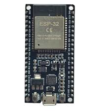
The ESP32 is a low-cost, low-power system on a chip (SoC) developed by Espressif Systems. It features integrated Wi-Fi and Bluetooth capabilities, making it an ideal choice for Internet of Things (IoT) applications, smart devices, and embedded systems. With its dual-core processor, extensive GPIO options, and support for various communication protocols, the ESP32 is a versatile and powerful microcontroller for a wide range of projects.

Explore Projects Built with esp32

Use Cirkit Designer to design, explore, and prototype these projects online. Some projects support real-time simulation. Click "Open Project" to start designing instantly!
ESP32-Controlled OLED Display and Servo with DotStar LED Strip and Audio Output
Image of Arena 2: A project utilizing esp32 in a practical application
This circuit features an ESP32 microcontroller driving a variety of components. It controls an OLED display for visual output, a DotStar LED strip for lighting effects, a PAM8403 audio amplifier connected to a speaker for sound output, and a PCA9685 PWM Servo Breakout to manage a servo motor. The ESP32 also interfaces with a piezo speaker for additional sound generation, and the circuit is powered by a 18650 Li-ion battery setup with a TP4056 charging module. The ESP32's embedded code handles the display animation on the OLED.
Cirkit Designer LogoOpen Project in Cirkit Designer
ESP32-Based Sensor Monitoring System with OLED Display and E-Stop
Image of MVP_design: A project utilizing esp32 in a practical application
This circuit features an ESP32 microcontroller that interfaces with a variety of sensors and output devices. It is powered by a Lipo battery through a buck converter, ensuring a stable voltage supply. The ESP32 collects data from a DHT11 temperature and humidity sensor and a vibration sensor, controls a buzzer, and displays information on an OLED screen. An emergency stop (E Stop) is connected for safety purposes, allowing the system to be quickly deactivated.
Cirkit Designer LogoOpen Project in Cirkit Designer
ESP32-Based Environmental Monitoring System with Motion Detection
Image of pro: A project utilizing esp32 in a practical application
This circuit features an ESP32 microcontroller on a baseboard that interfaces with a PIR sensor for motion detection, a DHT22 sensor for measuring temperature and humidity, and a BH1750 sensor for detecting ambient light levels. The ESP32 is configured to communicate with the BH1750 using I2C protocol, with GPIO22 and GPIO21 serving as the SCL and SDA lines, respectively. Power is supplied to the sensors from the ESP32's voltage output pins, and sensor outputs are connected to designated GPIO pins for data acquisition.
Cirkit Designer LogoOpen Project in Cirkit Designer
ESP32-Based Smart Weather Station with Wi-Fi Connectivity
Image of flowchart 3D: A project utilizing esp32 in a practical application
This circuit features an ESP32 microcontroller interfacing with various sensors and modules, including a DHT22 temperature and humidity sensor, an ESP32 CAM for image capture, an I2C LCD screen for display, a load cell with an HX711 interface for weight measurement, and a buzzer for audio alerts. The ESP32 handles data acquisition, processing, and communication with these peripherals to create a multi-functional monitoring and alert system.
Cirkit Designer LogoOpen Project in Cirkit Designer

Explore Projects Built with esp32

Use Cirkit Designer to design, explore, and prototype these projects online. Some projects support real-time simulation. Click "Open Project" to start designing instantly!
Image of Arena 2: A project utilizing esp32 in a practical application
ESP32-Controlled OLED Display and Servo with DotStar LED Strip and Audio Output
This circuit features an ESP32 microcontroller driving a variety of components. It controls an OLED display for visual output, a DotStar LED strip for lighting effects, a PAM8403 audio amplifier connected to a speaker for sound output, and a PCA9685 PWM Servo Breakout to manage a servo motor. The ESP32 also interfaces with a piezo speaker for additional sound generation, and the circuit is powered by a 18650 Li-ion battery setup with a TP4056 charging module. The ESP32's embedded code handles the display animation on the OLED.
Cirkit Designer LogoOpen Project in Cirkit Designer
Image of MVP_design: A project utilizing esp32 in a practical application
ESP32-Based Sensor Monitoring System with OLED Display and E-Stop
This circuit features an ESP32 microcontroller that interfaces with a variety of sensors and output devices. It is powered by a Lipo battery through a buck converter, ensuring a stable voltage supply. The ESP32 collects data from a DHT11 temperature and humidity sensor and a vibration sensor, controls a buzzer, and displays information on an OLED screen. An emergency stop (E Stop) is connected for safety purposes, allowing the system to be quickly deactivated.
Cirkit Designer LogoOpen Project in Cirkit Designer
Image of pro: A project utilizing esp32 in a practical application
ESP32-Based Environmental Monitoring System with Motion Detection
This circuit features an ESP32 microcontroller on a baseboard that interfaces with a PIR sensor for motion detection, a DHT22 sensor for measuring temperature and humidity, and a BH1750 sensor for detecting ambient light levels. The ESP32 is configured to communicate with the BH1750 using I2C protocol, with GPIO22 and GPIO21 serving as the SCL and SDA lines, respectively. Power is supplied to the sensors from the ESP32's voltage output pins, and sensor outputs are connected to designated GPIO pins for data acquisition.
Cirkit Designer LogoOpen Project in Cirkit Designer
Image of flowchart 3D: A project utilizing esp32 in a practical application
ESP32-Based Smart Weather Station with Wi-Fi Connectivity
This circuit features an ESP32 microcontroller interfacing with various sensors and modules, including a DHT22 temperature and humidity sensor, an ESP32 CAM for image capture, an I2C LCD screen for display, a load cell with an HX711 interface for weight measurement, and a buzzer for audio alerts. The ESP32 handles data acquisition, processing, and communication with these peripherals to create a multi-functional monitoring and alert system.
Cirkit Designer LogoOpen Project in Cirkit Designer

Common Applications and Use Cases

  • IoT devices and smart home automation
  • Wireless sensor networks
  • Wearable electronics
  • Robotics and drones
  • Industrial automation
  • Prototyping and educational projects

Technical Specifications

The ESP32 is packed with features that make it suitable for both simple and complex applications. Below are its key technical specifications:

Key Technical Details

  • Processor: Dual-core Xtensa® 32-bit LX6 microprocessor
  • Clock Speed: Up to 240 MHz
  • RAM: 520 KB SRAM
  • Flash Memory: Typically 4 MB (varies by module)
  • Wi-Fi: 802.11 b/g/n (2.4 GHz)
  • Bluetooth: v4.2 BR/EDR and BLE
  • Operating Voltage: 3.3V
  • GPIO Pins: 34 (multipurpose, including ADC, DAC, PWM, I2C, SPI, UART)
  • ADC Channels: 18 (12-bit resolution)
  • DAC Channels: 2 (8-bit resolution)
  • Power Consumption: Ultra-low power modes available
  • Temperature Range: -40°C to +125°C

Pin Configuration and Descriptions

The ESP32 has a variety of pins for different functionalities. Below is a table summarizing the key pins:

Pin Name Function Description
GPIO0 Input/Output, Boot Mode Select Used for boot mode selection during startup.
GPIO2 Input/Output, ADC, PWM General-purpose pin with ADC and PWM capabilities.
GPIO12 Input/Output, ADC, Touch Sensor Can be used as an ADC input or capacitive touch sensor.
GPIO13 Input/Output, ADC, PWM General-purpose pin with ADC and PWM capabilities.
GPIO15 Input/Output, ADC, PWM General-purpose pin with ADC and PWM capabilities.
EN Enable Pin Active high; used to enable or reset the chip.
3V3 Power Supply Provides 3.3V power to the ESP32.
GND Ground Ground connection.
TX0 UART Transmit UART0 transmit pin for serial communication.
RX0 UART Receive UART0 receive pin for serial communication.

Note: The ESP32 has multiple GPIO pins that can be configured for various functions, such as I2C, SPI, UART, ADC, and PWM. Refer to the ESP32 datasheet for a complete pinout diagram.

Usage Instructions

How to Use the ESP32 in a Circuit

  1. Powering the ESP32:
    • The ESP32 operates at 3.3V. Ensure your power supply provides a stable 3.3V to the 3V3 pin.
    • Avoid supplying 5V directly to any GPIO pin, as this may damage the chip.
  2. Connecting to a Computer:
    • Use a USB-to-serial adapter or a development board (e.g., ESP32 DevKit) to connect the ESP32 to your computer.
    • Install the necessary drivers for the USB-to-serial chip (e.g., CP2102 or CH340).
  3. Programming the ESP32:
    • Use the Arduino IDE or Espressif's ESP-IDF (IoT Development Framework) to write and upload code.
    • Select the correct board and port in the IDE before uploading the code.

Important Considerations and Best Practices

  • GPIO Voltage Levels: Ensure all GPIO pins operate at 3.3V logic levels.
  • Boot Mode: GPIO0 must be pulled low during boot to enter programming mode.
  • Power Supply: Use a decoupling capacitor (e.g., 10 µF) near the power pins to stabilize the voltage.
  • Wi-Fi Antenna: Avoid placing metal objects near the onboard antenna to ensure optimal Wi-Fi performance.

Example Code for Arduino IDE

Below is an example of how to use the ESP32 to connect to a Wi-Fi network and blink an LED:

#include <WiFi.h> // Include the Wi-Fi library

// Replace with your network credentials
const char* ssid = "Your_SSID";
const char* password = "Your_PASSWORD";

void setup() {
  Serial.begin(115200); // Initialize serial communication
  pinMode(2, OUTPUT);   // Set GPIO2 as an output pin (connected to an LED)

  // Connect to Wi-Fi
  Serial.print("Connecting to Wi-Fi");
  WiFi.begin(ssid, password);
  while (WiFi.status() != WL_CONNECTED) {
    delay(500);
    Serial.print(".");
  }
  Serial.println("\nWi-Fi connected!");
}

void loop() {
  digitalWrite(2, HIGH); // Turn the LED on
  delay(1000);           // Wait for 1 second
  digitalWrite(2, LOW);  // Turn the LED off
  delay(1000);           // Wait for 1 second
}

Note: Replace Your_SSID and Your_PASSWORD with your Wi-Fi network credentials.

Troubleshooting and FAQs

Common Issues and Solutions

  1. ESP32 Not Connecting to Wi-Fi:

    • Ensure the SSID and password are correct.
    • Check if the Wi-Fi network is within range.
    • Verify that the ESP32 is powered properly.
  2. Upload Fails in Arduino IDE:

    • Ensure the correct board and port are selected in the IDE.
    • Hold the BOOT button (if available) while uploading the code.
  3. ESP32 Keeps Resetting:

    • Check the power supply for stability. Use a capacitor to filter noise.
    • Avoid connecting peripherals that draw excessive current.
  4. GPIO Pin Not Working:

    • Verify the pin's configuration in the code.
    • Ensure the pin is not being used for another function (e.g., boot mode).

FAQs

  • Q: Can the ESP32 operate on 5V?

    • A: No, the ESP32 operates at 3.3V. However, many development boards include a voltage regulator to accept 5V input.
  • Q: How do I reset the ESP32?

    • A: Press the EN (Enable) button on the development board to reset the ESP32.
  • Q: Can I use the ESP32 with Bluetooth and Wi-Fi simultaneously?

    • A: Yes, the ESP32 supports simultaneous use of Bluetooth and Wi-Fi, but performance may vary depending on the application.

This concludes the ESP32 documentation. For more details, refer to the official Espressif documentation.