Cirkit Designer Logo
Cirkit Designer
Your all-in-one circuit design IDE
Home / 
Component Documentation

How to Use ZS-X11h: Examples, Pinouts, and Specs

Image of ZS-X11h
Cirkit Designer LogoDesign with ZS-X11h in Cirkit Designer

Introduction

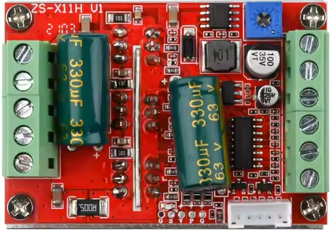
The ZS-X11h is a versatile electronic component designed for signal processing and control applications. Manufactured by China NoName, this component is widely used in circuits requiring efficient data handling and communication. Its multiple input and output channels make it suitable for a variety of use cases, including automation systems, sensor interfacing, and communication modules.

Explore Projects Built with ZS-X11h

Use Cirkit Designer to design, explore, and prototype these projects online. Some projects support real-time simulation. Click "Open Project" to start designing instantly!
Satellite-Based Timing and Navigation System with SDR and Atomic Clock Synchronization
Image of GPS 시스템 측정 구성도_Confirm: A project utilizing ZS-X11h in a practical application
This circuit appears to be a complex system involving power supply management, GPS and timing synchronization, and data communication. It includes a SI-TEX G1 Satellite Compass for GPS data, an XHTF1021 Atomic Rubidium Clock for precise timing, and Ettus USRP B200 units for software-defined radio communication. Power is supplied through various SMPS units and distributed via terminal blocks and DC jacks. Data communication is facilitated by Beelink MINI S12 N95 computers, RS232 splitters, and a 1000BASE-T Media Converter for network connectivity. RF Directional Couplers are used to interface antennas with the USRP units, and the entire system is likely contained within cases for protection and organization.
Cirkit Designer LogoOpen Project in Cirkit Designer
ESP32-Based Smart Energy Monitoring and Control System
Image of SMART SOCKET: A project utilizing ZS-X11h in a practical application
This circuit is designed to monitor AC voltage and current using ZMPT101B and ZMCT103C sensors, respectively, with an ESP32 microcontroller processing the sensor outputs. The XL4015 step-down module regulates the power supply to provide a stable voltage to the sensors, the ESP32, and an LCD I2C display. The ESP32 controls a 4-channel relay module for switching AC loads, and the system's operation can be interacted with via the LCD display and a push switch.
Cirkit Designer LogoOpen Project in Cirkit Designer
ESP32C3-Based Smart AC Light Controller with Voltage Sensing
Image of plugins: A project utilizing ZS-X11h in a practical application
This circuit appears to be a smart AC power control system. The XIAO ESP32C3 microcontroller is used to monitor AC voltage through the ZMPT101B module and to control a 12v Relay, which in turn switches an AC Bulb on or off. The Mini AC-DC module provides the 5V power required by the microcontroller and the relay, while the AC Wire provides the AC power to the system.
Cirkit Designer LogoOpen Project in Cirkit Designer
Solar-Powered GSM/GPRS+GPS Tracker with Seeeduino XIAO
Image of SOS System : A project utilizing ZS-X11h in a practical application
This circuit features an Ai Thinker A9G development board for GSM/GPRS and GPS/BDS connectivity, interfaced with a Seeeduino XIAO microcontroller for control and data processing. A solar cell, coupled with a TP4056 charging module, charges a 3.3V battery, which powers the system through a 3.3V regulator ensuring stable operation. The circuit likely serves for remote data communication and location tracking, with the capability to be powered by renewable energy and interfaced with additional sensors or input devices via the Seeeduino XIAO.
Cirkit Designer LogoOpen Project in Cirkit Designer

Explore Projects Built with ZS-X11h

Use Cirkit Designer to design, explore, and prototype these projects online. Some projects support real-time simulation. Click "Open Project" to start designing instantly!
Image of GPS 시스템 측정 구성도_Confirm: A project utilizing ZS-X11h in a practical application
Satellite-Based Timing and Navigation System with SDR and Atomic Clock Synchronization
This circuit appears to be a complex system involving power supply management, GPS and timing synchronization, and data communication. It includes a SI-TEX G1 Satellite Compass for GPS data, an XHTF1021 Atomic Rubidium Clock for precise timing, and Ettus USRP B200 units for software-defined radio communication. Power is supplied through various SMPS units and distributed via terminal blocks and DC jacks. Data communication is facilitated by Beelink MINI S12 N95 computers, RS232 splitters, and a 1000BASE-T Media Converter for network connectivity. RF Directional Couplers are used to interface antennas with the USRP units, and the entire system is likely contained within cases for protection and organization.
Cirkit Designer LogoOpen Project in Cirkit Designer
Image of SMART SOCKET: A project utilizing ZS-X11h in a practical application
ESP32-Based Smart Energy Monitoring and Control System
This circuit is designed to monitor AC voltage and current using ZMPT101B and ZMCT103C sensors, respectively, with an ESP32 microcontroller processing the sensor outputs. The XL4015 step-down module regulates the power supply to provide a stable voltage to the sensors, the ESP32, and an LCD I2C display. The ESP32 controls a 4-channel relay module for switching AC loads, and the system's operation can be interacted with via the LCD display and a push switch.
Cirkit Designer LogoOpen Project in Cirkit Designer
Image of plugins: A project utilizing ZS-X11h in a practical application
ESP32C3-Based Smart AC Light Controller with Voltage Sensing
This circuit appears to be a smart AC power control system. The XIAO ESP32C3 microcontroller is used to monitor AC voltage through the ZMPT101B module and to control a 12v Relay, which in turn switches an AC Bulb on or off. The Mini AC-DC module provides the 5V power required by the microcontroller and the relay, while the AC Wire provides the AC power to the system.
Cirkit Designer LogoOpen Project in Cirkit Designer
Image of SOS System : A project utilizing ZS-X11h in a practical application
Solar-Powered GSM/GPRS+GPS Tracker with Seeeduino XIAO
This circuit features an Ai Thinker A9G development board for GSM/GPRS and GPS/BDS connectivity, interfaced with a Seeeduino XIAO microcontroller for control and data processing. A solar cell, coupled with a TP4056 charging module, charges a 3.3V battery, which powers the system through a 3.3V regulator ensuring stable operation. The circuit likely serves for remote data communication and location tracking, with the capability to be powered by renewable energy and interfaced with additional sensors or input devices via the Seeeduino XIAO.
Cirkit Designer LogoOpen Project in Cirkit Designer

Common Applications

  • Signal processing in automation systems
  • Sensor data acquisition and control
  • Communication modules in IoT devices
  • General-purpose control in embedded systems

Technical Specifications

The ZS-X11h is designed to operate efficiently in a wide range of electronic systems. Below are its key technical details:

Key Specifications

Parameter Value
Operating Voltage 3.3V to 5V
Maximum Current 50mA
Communication Protocol I2C, UART
Input Channels 4
Output Channels 4
Operating Temperature -20°C to 85°C
Dimensions 25mm x 15mm x 5mm

Pin Configuration

The ZS-X11h features a total of 8 pins, with the following configuration:

Pin Number Pin Name Description
1 VCC Power supply input (3.3V to 5V)
2 GND Ground
3 IN1 Input channel 1
4 IN2 Input channel 2
5 OUT1 Output channel 1
6 OUT2 Output channel 2
7 SDA I2C Data Line
8 SCL I2C Clock Line

Usage Instructions

The ZS-X11h is straightforward to integrate into a circuit. Below are the steps and considerations for using this component effectively.

How to Use

  1. Power the Component: Connect the VCC pin to a 3.3V or 5V power source and the GND pin to the ground of your circuit.
  2. Connect Input Channels: Use the IN1 and IN2 pins to connect your input signals (e.g., sensors or other data sources).
  3. Connect Output Channels: Use the OUT1 and OUT2 pins to connect to the devices or modules you want to control.
  4. Communication Setup: If using I2C, connect the SDA and SCL pins to the corresponding pins on your microcontroller.
  5. Programming: Write the necessary code to configure and control the ZS-X11h. Below is an example for Arduino UNO.

Arduino UNO Example Code

#include <Wire.h> // Include the Wire library for I2C communication

#define ZS_X11H_ADDRESS 0x40 // Replace with the actual I2C address of ZS-X11h

void setup() {
  Wire.begin(); // Initialize I2C communication
  Serial.begin(9600); // Start serial communication for debugging

  // Send initialization command to ZS-X11h
  Wire.beginTransmission(ZS_X11H_ADDRESS);
  Wire.write(0x01); // Example command to initialize the component
  Wire.endTransmission();

  Serial.println("ZS-X11h initialized.");
}

void loop() {
  // Example: Read data from ZS-X11h
  Wire.beginTransmission(ZS_X11H_ADDRESS);
  Wire.write(0x02); // Command to request data
  Wire.endTransmission();

  Wire.requestFrom(ZS_X11H_ADDRESS, 2); // Request 2 bytes of data
  if (Wire.available() == 2) {
    int data = Wire.read() << 8 | Wire.read(); // Combine two bytes into an integer
    Serial.print("Data received: ");
    Serial.println(data);
  }

  delay(1000); // Wait 1 second before the next read
}

Best Practices

  • Ensure the operating voltage is within the specified range (3.3V to 5V).
  • Use pull-up resistors (typically 4.7kΩ) on the SDA and SCL lines for I2C communication.
  • Avoid exceeding the maximum current rating of 50mA to prevent damage.
  • Keep the component within the specified operating temperature range (-20°C to 85°C).

Troubleshooting and FAQs

Common Issues and Solutions

  1. No Response from the Component

    • Cause: Incorrect wiring or power supply.
    • Solution: Double-check the connections, ensuring VCC and GND are properly connected.
  2. I2C Communication Fails

    • Cause: Missing pull-up resistors on SDA and SCL lines.
    • Solution: Add 4.7kΩ pull-up resistors to the SDA and SCL lines.
  3. Incorrect Data Output

    • Cause: Faulty input signals or incorrect configuration.
    • Solution: Verify the input signals and ensure the component is properly initialized in the code.
  4. Overheating

    • Cause: Exceeding the maximum current rating.
    • Solution: Reduce the load on the output channels and ensure proper heat dissipation.

FAQs

Q: Can the ZS-X11h operate at 12V?
A: No, the ZS-X11h is designed to operate within a voltage range of 3.3V to 5V. Using 12V may damage the component.

Q: Is the ZS-X11h compatible with SPI communication?
A: No, the ZS-X11h supports I2C and UART communication protocols only.

Q: Can I use all input and output channels simultaneously?
A: Yes, all input and output channels can be used simultaneously, provided the total current does not exceed 50mA.

Q: What is the default I2C address of the ZS-X11h?
A: The default I2C address is 0x40, but refer to the datasheet or test your specific module to confirm.

By following this documentation, you can effectively integrate and troubleshoot the ZS-X11h in your projects.