Cirkit Designer Logo
Cirkit Designer
Your all-in-one circuit design IDE
Home / 
Component Documentation

How to Use ESP32CUSTOM: Examples, Pinouts, and Specs

Image of ESP32CUSTOM
Cirkit Designer LogoDesign with ESP32CUSTOM in Cirkit Designer

Introduction

The ESP32CUSTOM is a customizable version of the ESP32 microcontroller, designed for advanced IoT applications and rapid prototyping. It features integrated Wi-Fi and Bluetooth capabilities, making it ideal for wireless communication and smart device development. With its powerful dual-core processor and extensive GPIO options, the ESP32CUSTOM is a versatile solution for a wide range of projects, from home automation to industrial IoT systems.

Explore Projects Built with ESP32CUSTOM

Use Cirkit Designer to design, explore, and prototype these projects online. Some projects support real-time simulation. Click "Open Project" to start designing instantly!
ESP32-Controlled OLED Display and Servo with DotStar LED Strip and Audio Output
Image of Arena 2: A project utilizing ESP32CUSTOM in a practical application
This circuit features an ESP32 microcontroller driving a variety of components. It controls an OLED display for visual output, a DotStar LED strip for lighting effects, a PAM8403 audio amplifier connected to a speaker for sound output, and a PCA9685 PWM Servo Breakout to manage a servo motor. The ESP32 also interfaces with a piezo speaker for additional sound generation, and the circuit is powered by a 18650 Li-ion battery setup with a TP4056 charging module. The ESP32's embedded code handles the display animation on the OLED.
Cirkit Designer LogoOpen Project in Cirkit Designer
ESP32-Based Smart Display with Camera and Audio Alert System
Image of cam_circuit_design: A project utilizing ESP32CUSTOM in a practical application
This circuit features two ESP32 microcontrollers, one standard 30-pin version and one ESP32-CAM module, both sharing a common ground and power supply. The 30-pin ESP32 is interfaced with an I2C LCD 16x2 Screen for display purposes, using its I2C pins (D21 for SDA and D22 for SCL), and controls a buzzer connected to pin D23. Additionally, the ESP32-CAM is connected to the 30-pin ESP32 via serial communication through pins TX2 and RX2 for potential image data transfer.
Cirkit Designer LogoOpen Project in Cirkit Designer
ESP32-Based Smart Weather Station with Wi-Fi Connectivity
Image of flowchart 3D: A project utilizing ESP32CUSTOM in a practical application
This circuit features an ESP32 microcontroller interfacing with various sensors and modules, including a DHT22 temperature and humidity sensor, an ESP32 CAM for image capture, an I2C LCD screen for display, a load cell with an HX711 interface for weight measurement, and a buzzer for audio alerts. The ESP32 handles data acquisition, processing, and communication with these peripherals to create a multi-functional monitoring and alert system.
Cirkit Designer LogoOpen Project in Cirkit Designer
ESP32-Based Sensor Monitoring System with OLED Display and E-Stop
Image of MVP_design: A project utilizing ESP32CUSTOM in a practical application
This circuit features an ESP32 microcontroller that interfaces with a variety of sensors and output devices. It is powered by a Lipo battery through a buck converter, ensuring a stable voltage supply. The ESP32 collects data from a DHT11 temperature and humidity sensor and a vibration sensor, controls a buzzer, and displays information on an OLED screen. An emergency stop (E Stop) is connected for safety purposes, allowing the system to be quickly deactivated.
Cirkit Designer LogoOpen Project in Cirkit Designer

Explore Projects Built with ESP32CUSTOM

Use Cirkit Designer to design, explore, and prototype these projects online. Some projects support real-time simulation. Click "Open Project" to start designing instantly!
Image of Arena 2: A project utilizing ESP32CUSTOM in a practical application
ESP32-Controlled OLED Display and Servo with DotStar LED Strip and Audio Output
This circuit features an ESP32 microcontroller driving a variety of components. It controls an OLED display for visual output, a DotStar LED strip for lighting effects, a PAM8403 audio amplifier connected to a speaker for sound output, and a PCA9685 PWM Servo Breakout to manage a servo motor. The ESP32 also interfaces with a piezo speaker for additional sound generation, and the circuit is powered by a 18650 Li-ion battery setup with a TP4056 charging module. The ESP32's embedded code handles the display animation on the OLED.
Cirkit Designer LogoOpen Project in Cirkit Designer
Image of cam_circuit_design: A project utilizing ESP32CUSTOM in a practical application
ESP32-Based Smart Display with Camera and Audio Alert System
This circuit features two ESP32 microcontrollers, one standard 30-pin version and one ESP32-CAM module, both sharing a common ground and power supply. The 30-pin ESP32 is interfaced with an I2C LCD 16x2 Screen for display purposes, using its I2C pins (D21 for SDA and D22 for SCL), and controls a buzzer connected to pin D23. Additionally, the ESP32-CAM is connected to the 30-pin ESP32 via serial communication through pins TX2 and RX2 for potential image data transfer.
Cirkit Designer LogoOpen Project in Cirkit Designer
Image of flowchart 3D: A project utilizing ESP32CUSTOM in a practical application
ESP32-Based Smart Weather Station with Wi-Fi Connectivity
This circuit features an ESP32 microcontroller interfacing with various sensors and modules, including a DHT22 temperature and humidity sensor, an ESP32 CAM for image capture, an I2C LCD screen for display, a load cell with an HX711 interface for weight measurement, and a buzzer for audio alerts. The ESP32 handles data acquisition, processing, and communication with these peripherals to create a multi-functional monitoring and alert system.
Cirkit Designer LogoOpen Project in Cirkit Designer
Image of MVP_design: A project utilizing ESP32CUSTOM in a practical application
ESP32-Based Sensor Monitoring System with OLED Display and E-Stop
This circuit features an ESP32 microcontroller that interfaces with a variety of sensors and output devices. It is powered by a Lipo battery through a buck converter, ensuring a stable voltage supply. The ESP32 collects data from a DHT11 temperature and humidity sensor and a vibration sensor, controls a buzzer, and displays information on an OLED screen. An emergency stop (E Stop) is connected for safety purposes, allowing the system to be quickly deactivated.
Cirkit Designer LogoOpen Project in Cirkit Designer

Common Applications and Use Cases

  • Smart home devices (e.g., smart lights, thermostats)
  • IoT sensors and data loggers
  • Wearable technology
  • Wireless communication hubs
  • Robotics and automation systems
  • Prototyping and educational projects

Technical Specifications

The ESP32CUSTOM offers robust performance and flexibility. Below are its key technical specifications:

Parameter Value
Microcontroller Dual-core Xtensa® 32-bit LX6
Clock Speed Up to 240 MHz
Flash Memory 4 MB (customizable up to 16 MB)
SRAM 520 KB
Wi-Fi 802.11 b/g/n (2.4 GHz)
Bluetooth v4.2 BR/EDR and BLE
Operating Voltage 3.3V
Input Voltage Range 3.0V - 3.6V
GPIO Pins 34 (configurable for digital/analog use)
ADC Channels 18 (12-bit resolution)
DAC Channels 2 (8-bit resolution)
Communication Protocols UART, SPI, I2C, I2S, CAN, PWM
Power Consumption Ultra-low power modes available
Operating Temperature -40°C to 85°C

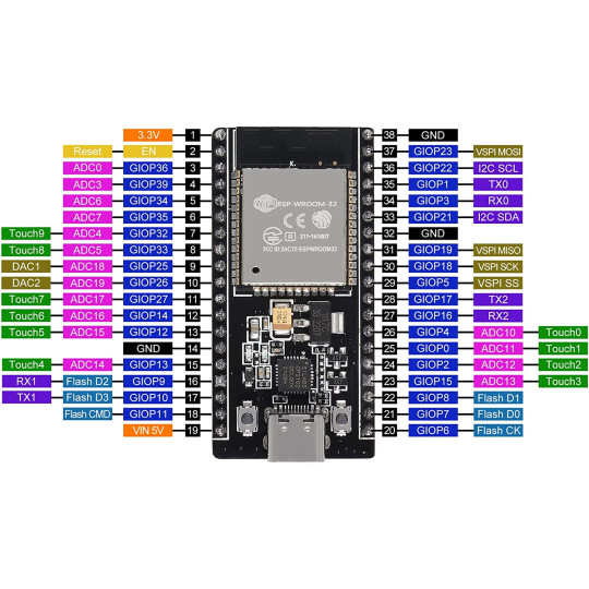
Pin Configuration and Descriptions

The ESP32CUSTOM has a total of 38 pins, with the following key pin assignments:

Pin Number Pin Name Description
1 EN Enable pin (active high)
2 IO0 GPIO0, used for boot mode selection
3 IO1 GPIO1, UART TX
4 IO2 GPIO2, general-purpose I/O
5 IO3 GPIO3, UART RX
6-11 IO4-IO9 General-purpose I/O pins
12 GND Ground
13 3V3 3.3V power output
14-38 IO10-IO34 Configurable GPIO pins

Note: Some GPIO pins have specific functions (e.g., ADC, PWM). Refer to the ESP32CUSTOM datasheet for detailed pin multiplexing information.

Usage Instructions

How to Use the ESP32CUSTOM in a Circuit

  1. Powering the ESP32CUSTOM:

    • Connect the 3.3V pin to a stable 3.3V power source.
    • Ensure the GND pin is connected to the ground of your circuit.
    • Avoid exceeding the input voltage range (3.0V - 3.6V) to prevent damage.
  2. Programming the ESP32CUSTOM:

    • Use a USB-to-serial adapter to connect the ESP32CUSTOM to your computer.
    • Install the necessary drivers and the Arduino IDE or ESP-IDF development environment.
    • Select the appropriate board settings in your IDE (e.g., "ESP32 Dev Module").
  3. Connecting Peripherals:

    • Use the GPIO pins for interfacing with sensors, actuators, and other devices.
    • Configure the pins in your code for digital or analog input/output as needed.
  4. Wireless Communication:

    • Use the built-in Wi-Fi and Bluetooth modules for wireless connectivity.
    • Configure the network settings in your code to connect to a Wi-Fi network or pair with Bluetooth devices.

Important Considerations and Best Practices

  • Power Supply: Use a low-noise, regulated power supply to ensure stable operation.
  • GPIO Voltage Levels: The GPIO pins operate at 3.3V logic levels. Avoid applying 5V to any GPIO pin.
  • Boot Mode: To enter programming mode, hold the IO0 pin low while resetting the board.
  • Heat Management: If running at high clock speeds or under heavy load, consider adding a heatsink for thermal management.

Example Code for Arduino UNO Integration

The following example demonstrates how to connect the ESP32CUSTOM to a Wi-Fi network and send data to a server:

#include <WiFi.h> // Include the Wi-Fi library

// Replace with your network credentials
const char* ssid = "Your_SSID";
const char* password = "Your_PASSWORD";

void setup() {
  Serial.begin(115200); // Initialize serial communication
  delay(1000);

  // Connect to Wi-Fi
  Serial.println("Connecting to Wi-Fi...");
  WiFi.begin(ssid, password);

  while (WiFi.status() != WL_CONNECTED) {
    delay(500);
    Serial.print("."); // Print dots while connecting
  }

  Serial.println("\nConnected to Wi-Fi!");
  Serial.print("IP Address: ");
  Serial.println(WiFi.localIP()); // Print the assigned IP address
}

void loop() {
  // Add your main code here
}

Note: Replace Your_SSID and Your_PASSWORD with your Wi-Fi network credentials.

Troubleshooting and FAQs

Common Issues and Solutions

  1. ESP32CUSTOM Not Connecting to Wi-Fi:

    • Double-check the SSID and password in your code.
    • Ensure the Wi-Fi network is within range and not using unsupported security protocols.
  2. Board Not Detected by Computer:

    • Verify that the USB-to-serial adapter is properly connected.
    • Install the correct drivers for your operating system.
  3. GPIO Pins Not Responding:

    • Ensure the pins are correctly configured in your code.
    • Check for short circuits or incorrect wiring.
  4. Overheating:

    • Reduce the clock speed or workload.
    • Improve ventilation or add a heatsink.

FAQs

  • Q: Can I use 5V sensors with the ESP32CUSTOM?
    A: Yes, but you will need a level shifter to convert the 5V signals to 3.3V.

  • Q: How do I reset the ESP32CUSTOM?
    A: Press the EN pin or use the reset button (if available on your board).

  • Q: Can I use the ESP32CUSTOM with batteries?
    A: Yes, ensure the battery voltage is within the input range (3.0V - 3.6V) or use a voltage regulator.

This documentation provides a comprehensive guide to using the ESP32CUSTOM microcontroller. For further details, refer to the official datasheet and user manual.