How to Use PWM DC Motor Speed Control 5-16V - 10A: Examples, Pinouts, and Specs
Introduction
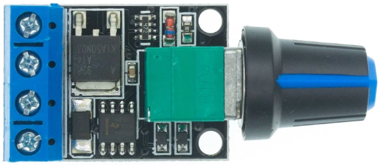
The PWM DC Motor Speed Control 5-16V - 10A is a versatile and efficient controller designed to regulate the speed of DC motors. By utilizing Pulse Width Modulation (PWM) technology, this component adjusts the motor speed by varying the duty cycle of the voltage supplied to the motor. It supports a wide voltage range of 5 to 16 volts and can handle currents up to 10 amps, making it suitable for a variety of applications.
Explore Projects Built with PWM DC Motor Speed Control 5-16V - 10A


Explore Projects Built with PWM DC Motor Speed Control 5-16V - 10A
Common Applications and Use Cases
- Robotics: Precise control of motor speed for robotic arms, wheels, and actuators.
- Electric vehicles: Speed regulation for small electric vehicles or scooters.
- Industrial automation: Controlling conveyor belts, fans, or pumps.
- DIY projects: Custom motorized systems such as remote-controlled cars or boats.
Technical Specifications
Key Technical Details
| Parameter | Value |
|---|---|
| Input Voltage Range | 5V to 16V |
| Maximum Current | 10A |
| Control Method | Pulse Width Modulation (PWM) |
| PWM Frequency | 20 kHz |
| Duty Cycle Range | 0% to 100% |
| Efficiency | >90% |
| Operating Temperature | -20°C to 60°C |
| Dimensions | 60mm x 40mm x 25mm |
Pin Configuration and Descriptions
| Pin Name | Description |
|---|---|
| VIN+ | Positive input voltage terminal (5V to 16V). Connect to the power source. |
| VIN- | Negative input voltage terminal. Connect to the ground of the power source. |
| MOTOR+ | Positive terminal for the DC motor. |
| MOTOR- | Negative terminal for the DC motor. |
| Potentiometer | Rotary knob to adjust the PWM duty cycle and control motor speed. |
Usage Instructions
How to Use the Component in a Circuit
Connect the Power Supply:
- Attach the positive terminal of your power source (5V to 16V) to the
VIN+pin. - Connect the negative terminal of the power source to the
VIN-pin.
- Attach the positive terminal of your power source (5V to 16V) to the
Connect the DC Motor:
- Connect the positive terminal of the DC motor to the
MOTOR+pin. - Connect the negative terminal of the DC motor to the
MOTOR-pin.
- Connect the positive terminal of the DC motor to the
Adjust the Speed:
- Use the potentiometer to vary the PWM duty cycle. Turning the knob clockwise increases the duty cycle, resulting in higher motor speed. Turning it counterclockwise decreases the speed.
Power On:
- Once all connections are secure, power on the circuit. The motor speed can now be controlled using the potentiometer.
Important Considerations and Best Practices
- Current Handling: Ensure the motor's current draw does not exceed 10A. Use a fuse or circuit breaker for added protection.
- Heat Dissipation: The controller may generate heat during operation. Use proper ventilation or a heatsink if necessary.
- Polarity: Double-check the polarity of the power supply and motor connections to avoid damage.
- PWM Frequency: The 20 kHz PWM frequency is above the audible range, ensuring quiet operation.
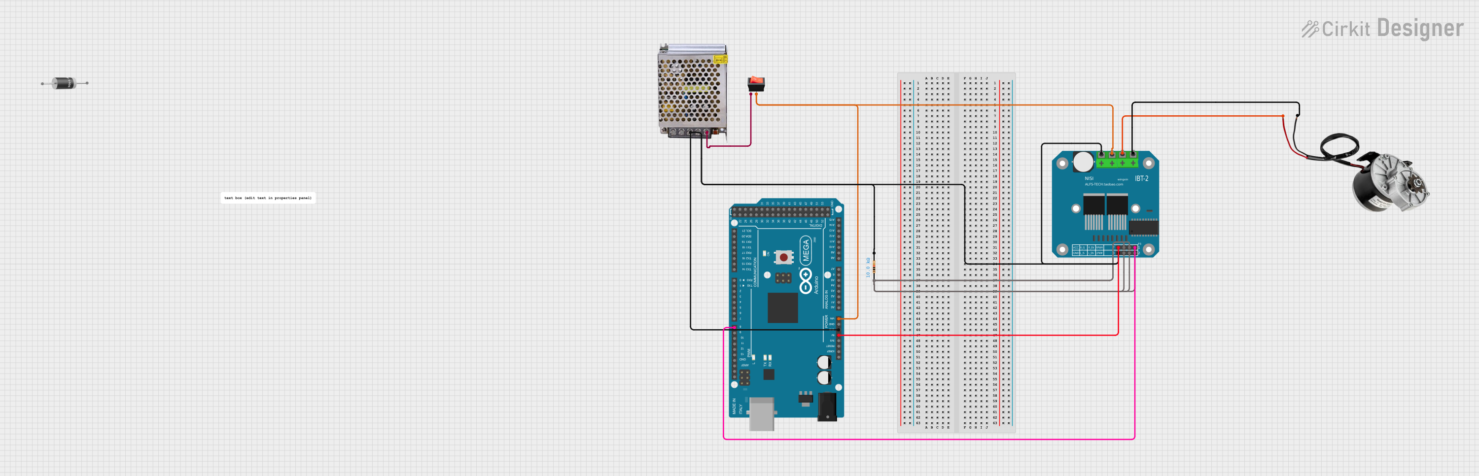
Example: Connecting to an Arduino UNO
While this component does not require an Arduino for basic operation, you can use an Arduino to generate a PWM signal for advanced control. Below is an example code to control the motor speed using an Arduino UNO:
// Example code to control a DC motor using Arduino UNO and PWM DC Motor Controller
// Connect the Arduino PWM pin (e.g., pin 9) to the PWM input of the motor controller.

const int pwmPin = 9; // PWM output pin connected to the motor controller

void setup() {
  pinMode(pwmPin, OUTPUT); // Set the PWM pin as an output
}

void loop() {
  // Gradually increase motor speed
  for (int dutyCycle = 0; dutyCycle <= 255; dutyCycle++) {
    analogWrite(pwmPin, dutyCycle); // Write PWM signal to the motor controller
    delay(10); // Small delay for smooth acceleration
  }

  // Gradually decrease motor speed
  for (int dutyCycle = 255; dutyCycle >= 0; dutyCycle--) {
    analogWrite(pwmPin, dutyCycle); // Write PWM signal to the motor controller
    delay(10); // Small delay for smooth deceleration
  }
}
Troubleshooting and FAQs
Common Issues and Solutions
Motor Does Not Spin:
- Cause: Incorrect wiring or loose connections.
- Solution: Double-check all connections, ensuring proper polarity and secure terminals.
Motor Spins at Full Speed Regardless of Potentiometer Position:
- Cause: Faulty potentiometer or damaged controller.
- Solution: Test the potentiometer with a multimeter. Replace if necessary.
Controller Overheats:
- Cause: Excessive current draw or poor ventilation.
- Solution: Ensure the motor's current is within the 10A limit. Add a heatsink or improve airflow.
PWM Signal from Arduino Not Working:
- Cause: Incorrect PWM pin or signal configuration.
- Solution: Verify the Arduino pin is capable of PWM output (e.g., pin 9 or 10). Check the code for errors.
FAQs
Can I use this controller with a 24V motor?
- No, the maximum input voltage is 16V. Using a higher voltage may damage the controller.
Is it possible to reverse the motor direction?
- Not directly. You will need an H-bridge circuit or a DPDT switch to reverse the motor polarity.
Can I control multiple motors with one controller?
- No, this controller is designed for a single motor. Use separate controllers for multiple motors.
What happens if the motor draws more than 10A?
- The controller may overheat or fail. Always ensure the motor's current is within the specified limit.