
How to Use 38mm 8x8 dot matrix column cathode led display: Examples, Pinouts, and Specs
 Design with 38mm 8x8 dot matrix column cathode led display in Cirkit Designer
Introduction
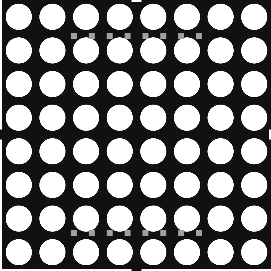
The 38mm 8x8 Dot Matrix Column Cathode LED Display is a compact and versatile display module consisting of an 8x8 grid of light-emitting diodes (LEDs). Each LED in the matrix can be individually controlled to display alphanumeric characters, symbols, or simple graphics. The column cathode configuration means that the cathodes (negative terminals) of the LEDs are grouped by columns, while the anodes (positive terminals) are grouped by rows.
This display is widely used in applications such as:
- Digital clocks and timers
- Scrolling text displays
- Status indicators
- Simple graphic displays in embedded systems
Its compact size and ease of integration make it a popular choice for hobbyists and professionals alike.
Explore Projects Built with 38mm 8x8 dot matrix column cathode led display
 Open Project in Cirkit Designer
 Open Project in Cirkit Designer
 Open Project in Cirkit Designer
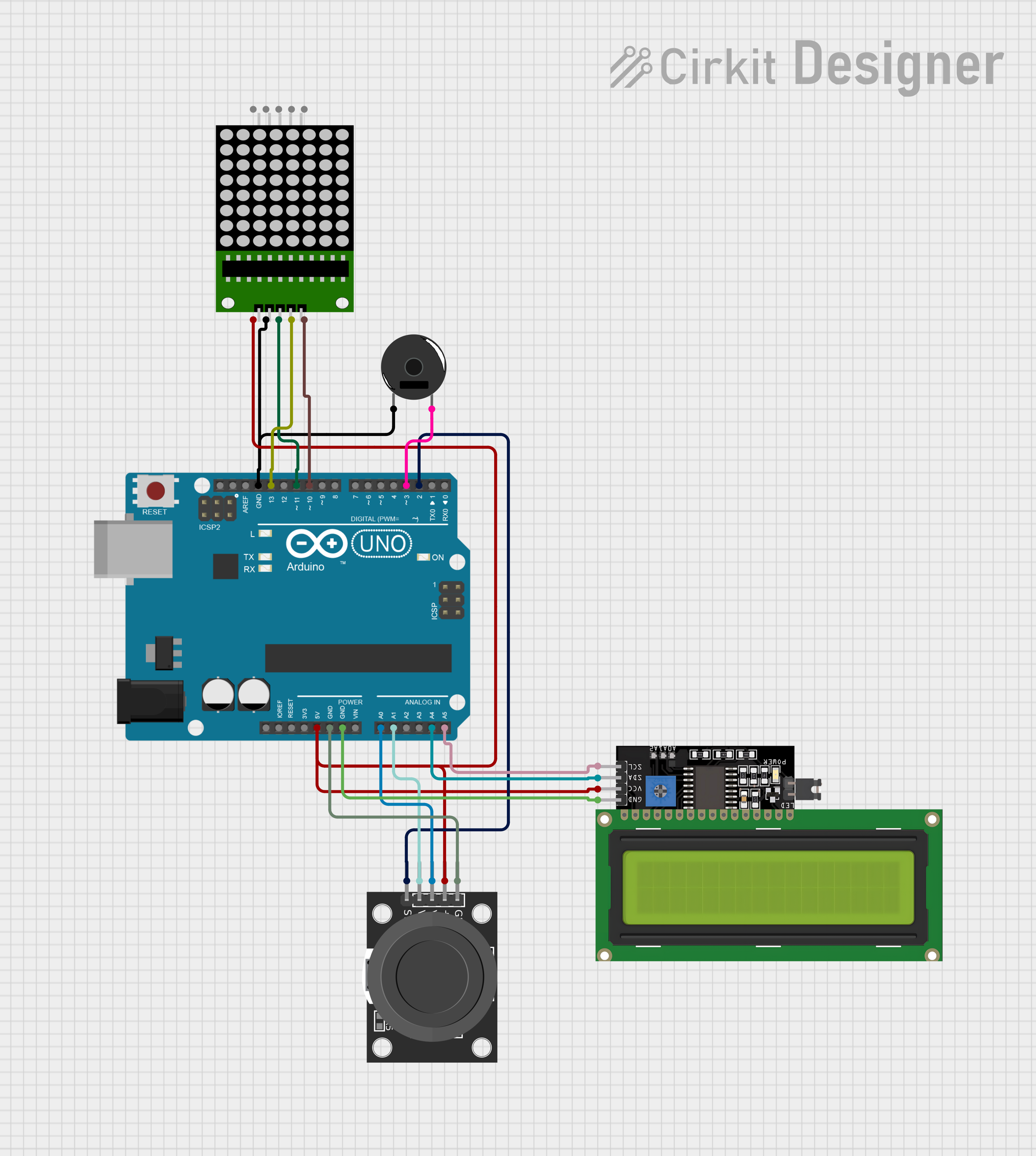 Open Project in Cirkit Designer
Explore Projects Built with 38mm 8x8 dot matrix column cathode led display
Open Project in Cirkit DesignerOpen Project in Cirkit DesignerOpen Project in Cirkit DesignerOpen Project in Cirkit DesignerTechnical Specifications
Key Technical Details
| Parameter | Value |
|---|---|
| Display Type | 8x8 Dot Matrix LED |
| Configuration | Column Cathode |
| LED Color | Red (or other variants) |
| Dimensions | 38mm x 38mm |
| Operating Voltage | 2.0V - 2.2V (per LED) |
| Forward Current (If) | 20mA (typical per LED) |
| Peak Forward Current | 100mA (maximum, duty cycle ≤ 1/10) |
| Reverse Voltage (Vr) | 5V (maximum) |
| Operating Temperature | -40°C to +85°C |
Pin Configuration and Descriptions
The 38mm 8x8 dot matrix display typically has 16 pins, with 8 pins for rows (anodes) and 8 pins for columns (cathodes). The pinout may vary slightly depending on the manufacturer, so always refer to the datasheet for your specific module.
| Pin Number | Description | Function |
|---|---|---|
| 1 | Row 1 (Anode) | Controls the first row of LEDs |
| 2 | Row 2 (Anode) | Controls the second row of LEDs |
| 3 | Row 3 (Anode) | Controls the third row of LEDs |
| 4 | Row 4 (Anode) | Controls the fourth row of LEDs |
| 5 | Row 5 (Anode) | Controls the fifth row of LEDs |
| 6 | Row 6 (Anode) | Controls the sixth row of LEDs |
| 7 | Row 7 (Anode) | Controls the seventh row of LEDs |
| 8 | Row 8 (Anode) | Controls the eighth row of LEDs |
| 9 | Column 1 (Cathode) | Controls the first column of LEDs |
| 10 | Column 2 (Cathode) | Controls the second column of LEDs |
| 11 | Column 3 (Cathode) | Controls the third column of LEDs |
| 12 | Column 4 (Cathode) | Controls the fourth column of LEDs |
| 13 | Column 5 (Cathode) | Controls the fifth column of LEDs |
| 14 | Column 6 (Cathode) | Controls the sixth column of LEDs |
| 15 | Column 7 (Cathode) | Controls the seventh column of LEDs |
| 16 | Column 8 (Cathode) | Controls the eighth column of LEDs |
Usage Instructions
How to Use the Component in a Circuit
- Power Requirements: Ensure that the forward voltage and current ratings of the LEDs are not exceeded. Use current-limiting resistors (typically 220Ω to 330Ω) in series with the anodes or cathodes to prevent damage to the LEDs.
- Multiplexing: Since the display has 64 LEDs but only 16 pins, it requires multiplexing to control individual LEDs. This can be achieved using a microcontroller or dedicated driver ICs like the MAX7219.
- Connections:
- Connect the row pins (anodes) to the microcontroller or driver IC.
- Connect the column pins (cathodes) to the microcontroller or driver IC.
- Use transistors or MOSFETs if the microcontroller cannot source/sink sufficient current.
Example: Connecting to an Arduino UNO
The following example demonstrates how to control the display using an Arduino UNO and a MAX7219 driver IC.
Circuit Diagram
- Connect the 8x8 dot matrix display to the MAX7219 as per the datasheet.
- Connect the MAX7219 to the Arduino UNO:
- DIN to Arduino pin 11 (MOSI)
- CLK to Arduino pin 13 (SCK)
- CS to Arduino pin 10
- VCC to 5V
- GND to GND
Arduino Code
#include <LedControl.h> // Include the LedControl library

// Initialize the MAX7219 with DIN=11, CLK=13, CS=10
LedControl lc = LedControl(11, 13, 10, 1);

void setup() {
  lc.shutdown(0, false); // Wake up the MAX7219
  lc.setIntensity(0, 8); // Set brightness level (0-15)
  lc.clearDisplay(0);    // Clear the display
}

void loop() {
  // Display a simple pattern (e.g., a diagonal line)
  for (int i = 0; i < 8; i++) {
    lc.setLed(0, i, i, true); // Turn on LED at row i, column i
    delay(200);               // Wait for 200ms
  }
  delay(1000);                // Pause for 1 second
  lc.clearDisplay(0);         // Clear the display
}
Important Considerations and Best Practices
- Current Limiting: Always use appropriate resistors to limit current through the LEDs.
- Heat Management: Avoid driving all LEDs at maximum brightness for extended periods to prevent overheating.
- Driver ICs: Use a driver IC like the MAX7219 for simplified control and reduced microcontroller pin usage.
- Power Supply: Ensure your power supply can handle the total current draw of the display.
Troubleshooting and FAQs
Common Issues
No LEDs Light Up:
- Check all connections and ensure the power supply is functioning.
- Verify that the current-limiting resistors are correctly installed.
- Ensure the microcontroller or driver IC is properly programmed.
Dim or Flickering LEDs:
- Check if the power supply can provide sufficient current.
- Verify that the multiplexing frequency is high enough to avoid visible flicker.
Incorrect Patterns Displayed:
- Double-check the wiring between the display, driver IC, and microcontroller.
- Ensure the software logic matches the pin configuration of the display.
FAQs
Q: Can I control the display without a driver IC?
A: Yes, but it requires more microcontroller pins and complex multiplexing logic. A driver IC like the MAX7219 simplifies the process significantly.
Q: Can I use this display with a 3.3V microcontroller?
A: Yes, but ensure the forward voltage of the LEDs is compatible, and use appropriate resistors or level shifters if needed.
Q: How do I display custom characters or graphics?
A: Create an 8x8 bitmap array where each bit represents an LED (1 = ON, 0 = OFF). Use this array to control the LEDs via your microcontroller or driver IC.
This concludes the documentation for the 38mm 8x8 Dot Matrix Column Cathode LED Display.